


Adjusting of the clearances should be performed with the closed valves at the compression
stroke in the following consequence:
a) to rotate the crankshaft clock-wise (looking from the side of the fan drive) till the moment
when the eduction valve of the first cylinder will be completely lifted (completely closed), after that to
rotate the shaft for 1/4 – 1/3 turns. In this position compression stroke will be finished in the first
cylinder and both valves of the cylinder will be closed;
b) to adjust clearances between the rocker panes and faces of the rods of the eduction and
induction valves of the first cylinder with the help of screwing of the adjusting screws of the rockers,
to lock the adjusting screws using the nuts. Nuts of the adjusting screws should be tightened with the
moment of force from 50 to 60 Nwm (from 5 to 6 kfg m);
c) consequently rotating the crankshaft clock-wise one should adjust the clearance between the
rocker panes and faces of the eduction and induction valve rods of the other cylinders according to the
enumeration а) and б) in the order of the cylinder work:
1) for engine
ЯМЗ-236М2 – 1–4–2–5–3–6;
2) for engine
ЯМЗ-238М2 – 1–5–4–2–6–3–7–8.
d) to check the correctness of the clearance adjustment. After the rotation of the crankshaft it is
permitted to change the clearance dimension because of the possible surface runout of the joining
parts of the valve operating mechanism within the range from 0.20 to 0.40 mm.
5.11 Installation of the nozzles
5.11.1. Set of nozzles should be installed at the engine which was installed during the
acceptance test of the high-pressure fuel pump for this engine.
5.11.2 Before the installation of the nozzles in the barrels of the cylinder heads one should
install a seal washer at each nozzle housing.
5.11.3 Fastening nuts of the nozzle clamps should be tightened with the moment of force from
50 to 62 Nwm (from 5.0 to 6.2 kfg·m).
5.12 Installation of the high-pressure fuel pump and adjustment of the lead angle of fuel
injection
5.12.1 Installation of the fuel pump at the engine and adjustment of the lead angle of fuel
injection should be performed in the following order:
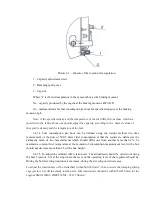
- to install and fasten the driven coupling 2 (picture 5.4) at the coupling of the lead injection 3 of
the high-pressure fuel pump;
- rotating the coupling of the lead injection 3 to install the bosses of the driven half-coupling in
the horizontal position, at that marking E at the coupling should be in zone of the indicator of the
beginning of the fuel injection fastened at the fuel pump body;
Summary of Contents for ???-236
Page 25: ...26...
Page 26: ...27 2...
Page 40: ......
Page 41: ......
Page 53: ......
Page 56: ......
Page 59: ......
Page 64: ...236 238 1003014 3 236 238 1003014 4 236 238 1003014...
Page 65: ......
Page 70: ......
Page 73: ......
Page 81: ......
Page 85: ......
Page 92: ......
Page 95: ......
Page 101: ......
Page 113: ......
Page 119: ......
Page 122: ......
Page 125: ......
Page 128: ......
Page 142: ......
Page 144: ......
Page 150: ......
Page 155: ......
Page 158: ......
Page 160: ......
Page 165: ......
Page 193: ...N u M a r Method defect detection and Dimension and parameter mm...
Page 201: ...4 Thread stripping M16 1 5 6H no more than two threads Inspection To calibrate the thread...


