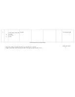


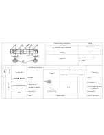
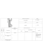

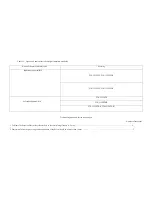
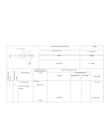
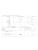
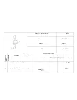


1115. Induction manifold
Name of the part or assembly unit
Marking
Right induction manifold
Left induction manifold
See the table 9
Material
Hardness
АК7М2Мг
80 НВ, no less
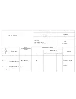
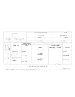
N
um
be
r o
f t
he
d
ef
ect
L
oc
at
ion o
f t
he
p
ic
tu
re
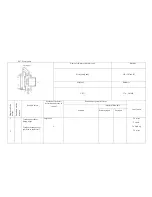
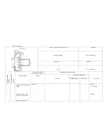
Possible defect
Method
defect detection and means
of control
Dimension and parameter, mm
Conclusion
nominal
maximum allowable
without repair
for repair
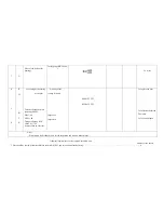
1
2
3
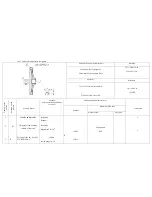
-
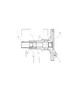
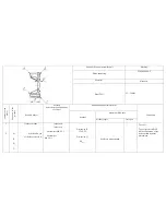
B
-
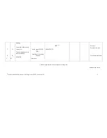
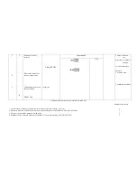
Cracks and breaks
Deformation of the joining
surfaces of the manifolds to
the cylinder head
Throughout corrosive
damage of the
Inspection.
Inspection. Slab
2-1-
1000х630.
Gauge 0.2 mm
Inspection
Flatness tolerance of the
surfaces B relatively to the
total joining flatness:
0.2
-
-
-
-
-
-
-
To weld
To build up
To process till the elimination
of the defect
Summary of Contents for ???-236
Page 25: ...26...
Page 26: ...27 2...
Page 40: ......
Page 41: ......
Page 53: ......
Page 56: ......
Page 59: ......
Page 64: ...236 238 1003014 3 236 238 1003014 4 236 238 1003014...
Page 65: ......
Page 70: ......
Page 73: ......
Page 81: ......
Page 85: ......
Page 92: ......
Page 95: ......
Page 101: ......
Page 113: ......
Page 119: ......
Page 122: ......
Page 125: ......
Page 128: ......
Page 142: ......
Page 144: ......
Page 150: ......
Page 155: ......
Page 158: ......
Page 160: ......
Page 165: ......
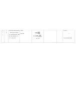
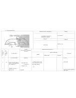
Page 193: ...N u M a r Method defect detection and Dimension and parameter mm...
Page 201: ...4 Thread stripping M16 1 5 6H no more than two threads Inspection To calibrate the thread...


