2 - 18
SPEC
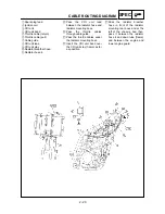
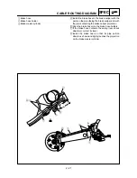
CABLE ROUTING DIAGRAM
EC240000
CABLE ROUTING DIAGRAM
1
Hose guide
2
Brake hose
3
Fuel tank breather hose
4
Engine stop switch lead
5
Oil tank breather hose
6
Sub-wire harness
7
Neutral switch lead
8
Cable guide
9
Cylinder head breather hose
0
CDI magneto lead
A
Radiator breather hose
B
Carburetor breather hose
C
Carburetor overflow hose
D
Ignition coil lead
E
CDI unit lead
Å
Pass the fuel tank breather hose
between the handlebar and ten-
sion bar, then insert its end into
the hole of the number plate.
ı
Fasten the engine stop switch
lead and ignition coil lead of the
sub-wire harness.
Ç
Fasten the sub-wire harness
and engine stop switch lead.
Fasten the engine stop switch
lead at its protecting tube.
Î
Fasten the sub-wire harness
and engine stop switch leads.
‰
Pass the sub-wire harness
between upper engine brackets.
Ï
Fasten the sub-wire harness.
Ì
Fasten the throttle position sen-
sor lead.
Ó
Pass the carburetor breather
hose and overflow hose
between the connecting rod and
cross tube (frame).
È
Fasten the neutral switch lead
on the oil hose.
Ô
Pass the clutch cable through
the cable guide.
Fasten the cylinder head
breather hose and neutral switch
lead.
Ò
Fasten the neutral switch lead.


