MTi 1-series User Manual
Xsens MTi User Manual Repository
Datasheet
Copyright © 2021 Xsens
Page 28
The user can configure the MTi 1-series module to communicate over UART in half-duplex
mode. The UART frame configuration is 8 data bits, no parity and 1 stop bit (8N1). In addition to
the RX and TX pins, the modules use control lines nRE and DE. The modules use these control
outputs to drive the TX signal on a shared medium and to drive the signal of the shared medium
on the RX signal.
A typical use case for this mode is to control an RS485 transceiver where the shared medium is
the RS485 signal, and the nRE and DE lines control the buffers inside the transceiver.
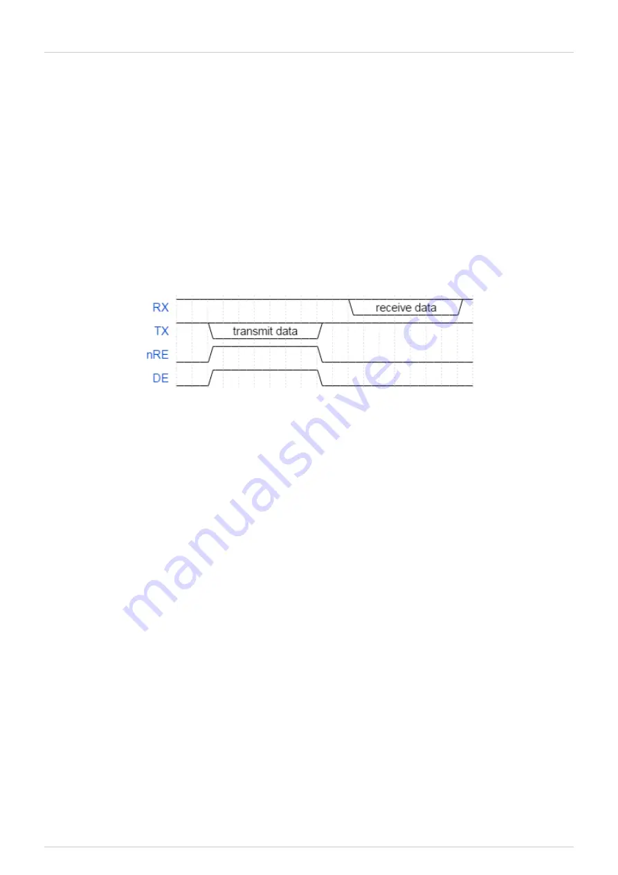
When the module is transmitting data on its TX pin it will raise both the nRE and DE lines, else it
will pull these lines low. The below figure depicts the behaviour of the involved signals.
Behaviour of the nRE and DE lines
Note that in this mode the UART of the MTi 1-s itself is still operating full duplex.
UART full duplex with RTS/CTS flow control
The user can configure the MTi 1-s module to communicate over UART in full duplex mode with
RTS/CTS flow control. The UART frame configuration is 8 data bits, no parity and 1 stop bit
(8N1). In addition to the RX and TX signals for data communication, the module uses the RTS
and CTS signals for hardware flow control.
The CTS signal is an input for the module. The module checks the state of the CTS line at the
start of every byte it transmits. If CTS is low, the module transmits the byte. Otherwise, it
postpones transmission until CTS is lowered. When, during the transmission of a byte, the user
raises the CTS signal, then the module completes transmission of that byte before postponing
further output. The module will not retransmit this byte. The figure below shows the behaviour
of the TX and CTS lines.


