(2) -1 means running in the opposite direction. The current encoder value is:
(U0-57-65535)*1+(U0-58-65535)*2^16+(U0- 59-65535)*2^32.
If the position is read by XINJE HMI and the U0-57 (Modbus address is decimal 4153) double-word is
read, the high-low byte exchange should be selected. If communicating with Xinje PLC, direct
double-word reading is ok.
23-bit absolute value encoder, one-cycle pulse number is 8388608.
First read the U0-60 (0x103C) value
(1) 0 means running in the positive direction. The current encoder value is
U0-57*1+U0-58*2^16+U0-59*2^32.
(2) -1 means running in the opposite direction. The current encoder value is:
[(65536 - U0-57)* 1 + (65535-U0-58)* 2
16
+ (65535 - U0-59)* 2
32
]*(-1).
Communication parameter description
RS485 default communication parameters: baud rate 19200 bps; data bit 8; stop bit 1; even parity;
Modbus station number 1.
Note: refer to chapter 8.2 for communication parameters.
5.6.5 Reset absolute position
Parameters
Name
F1-06
Clear the turns of absolute
encoder
U0-94
Relative
encoder
feedback
value which can be reset
U0-95
U0-96
U0-97
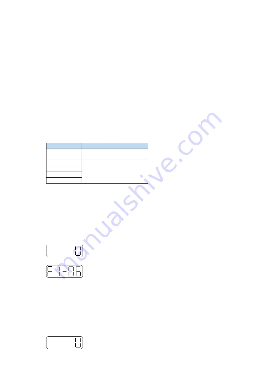
F1-06 clear the turns
Encoder turns clearing should be done when servo driver is bb. The clearing methods include servo
panel clearing and Modbus-RTU communication clearing. After the operation, U0-91 is 0,
U0-57~U0-59 will change.
1.
Servo panel clearing
Enter parameter F1-06 when servo is in bb state:
Press
【
INC
】
to 1, and keep press
【
ENT
】
to confirm and exit.
Clear the absolute encoder turns through F1-06 on the servo panel.
2.
Modbus-RTU communication clearing
Write 1 to the Modbus address 0x2106 to clear the turns.
It will take effective when servo is in bb state, after clearing, write 0 in 0x2106.
F1-06 zero position calibration
1. Calibrate through the servo panel
Enter F1-06 when servo is in bb status:
Press
【
INC
】
to 3 and long press
【
ENT
】
to confirm and exit.
Summary of Contents for DS5K Series
Page 1: ...DS5K series servo driver User manual WUXI XINJE ELECTRIC CO LTD Data No SC5 03 20200217 1 1...
Page 2: ......
Page 6: ......
Page 107: ...3 Set the auto tuning interface 4 Click ok to start inertia identification...
Page 114: ...3 set the auto tuning interface 4 click ok to estimate the inertia...
Page 116: ...6 Start auto tuning 7 Wait for the end of the auto tuning...
Page 120: ...with higher rigidity 6 Start auto tune 7 Open the servo enable then click ok...
Page 186: ...Appendix 9 Torque speed characteristic curve...
Page 187: ......
Page 188: ......


