internal
position
segment 3
distribute to input terminal
through P5-60
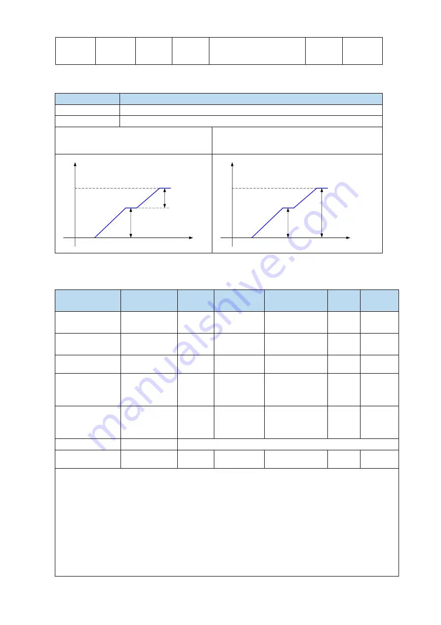
3. Positioning mode
n.xxx□
Meaning
0
Relative positioning
1
Absolute positioning
0: relative positioning
1: absolute positioning
(take the reference origin as the absolute
positioning origin)
P
t
Segment 1
Segment 2
P
t
Segment 1
Segment 2
5.3.3.3 Position segment 1 to 35 parameter settings
Parameter
Meaning
Default
setting
Unit
Range
Change
Effective
P4-10+
(
n-1
)
*7
Pulse number
(low bit)
0
1 pulse
-9999
~
9999
Servo
bb
At once
P4-11+
(
n-1
)
*7
Pulse number
(high bit)
0
10000 pulses
-32767
~
32767
Servo
bb
At once
P4-12+
(
n-1
)
*7
Speed
0
0.1rpm
0
~
65535
Servo
bb
At once
P4-13+
(
n-1
)
*7
Trapezoid
acceleration
time
0
ms
0
~
65535
Servo
bb
At once
P4-14+
(
n-1
)
*7
Trapezoid
deceleration
time
0
ms
0
~
65535
Servo
bb
At once
P4-15+
(
n-1
)
*7
Reserved
-
P4-16+
(
n-1
)
*7
Adjust time
0
ms
0
~
65535
Servo
bb
At once
Notes:
1. Set pulse number = pulse number (high bit) ×10000 + pulse number (low bit).
2. In formula P4-10+(n-1)*7, n is the segment no. of internal position; the range is 1~35. Segment 1~12 can
be set through the operate panel, segment 13~35 needs to write in parameters through communication
(RS232 or RS485).
3. If one of the segment speed is zero, servo will skip this segment and run the next segment.
4. In relative positioning mode, if one segment speed is not zero but the pulse number is zero, the motor
will not run, but the wait mode is effective. The servo will run the next segment when the adjust time is out.
5. In absolute positioning mode, if one segment speed is not zero but the pulse number is zero, the
motor will return to the reference origin with the speed of this segment.
6. In absolute positioning mode, if two consecutive segments speed are not zero, but the pulse number is
the same, the servo motor will not run but the wait mode is effective.
Summary of Contents for DS5K Series
Page 1: ...DS5K series servo driver User manual WUXI XINJE ELECTRIC CO LTD Data No SC5 03 20200217 1 1...
Page 2: ......
Page 6: ......
Page 107: ...3 Set the auto tuning interface 4 Click ok to start inertia identification...
Page 114: ...3 set the auto tuning interface 4 click ok to estimate the inertia...
Page 116: ...6 Start auto tuning 7 Wait for the end of the auto tuning...
Page 120: ...with higher rigidity 6 Start auto tune 7 Open the servo enable then click ok...
Page 186: ...Appendix 9 Torque speed characteristic curve...
Page 187: ......
Page 188: ......


