background image

All information, illustrations and specifications in this manual are based on the latest information  

available at the time of publication. We reserve the right to make changes at any time without notice.


52 

8.0. Service 

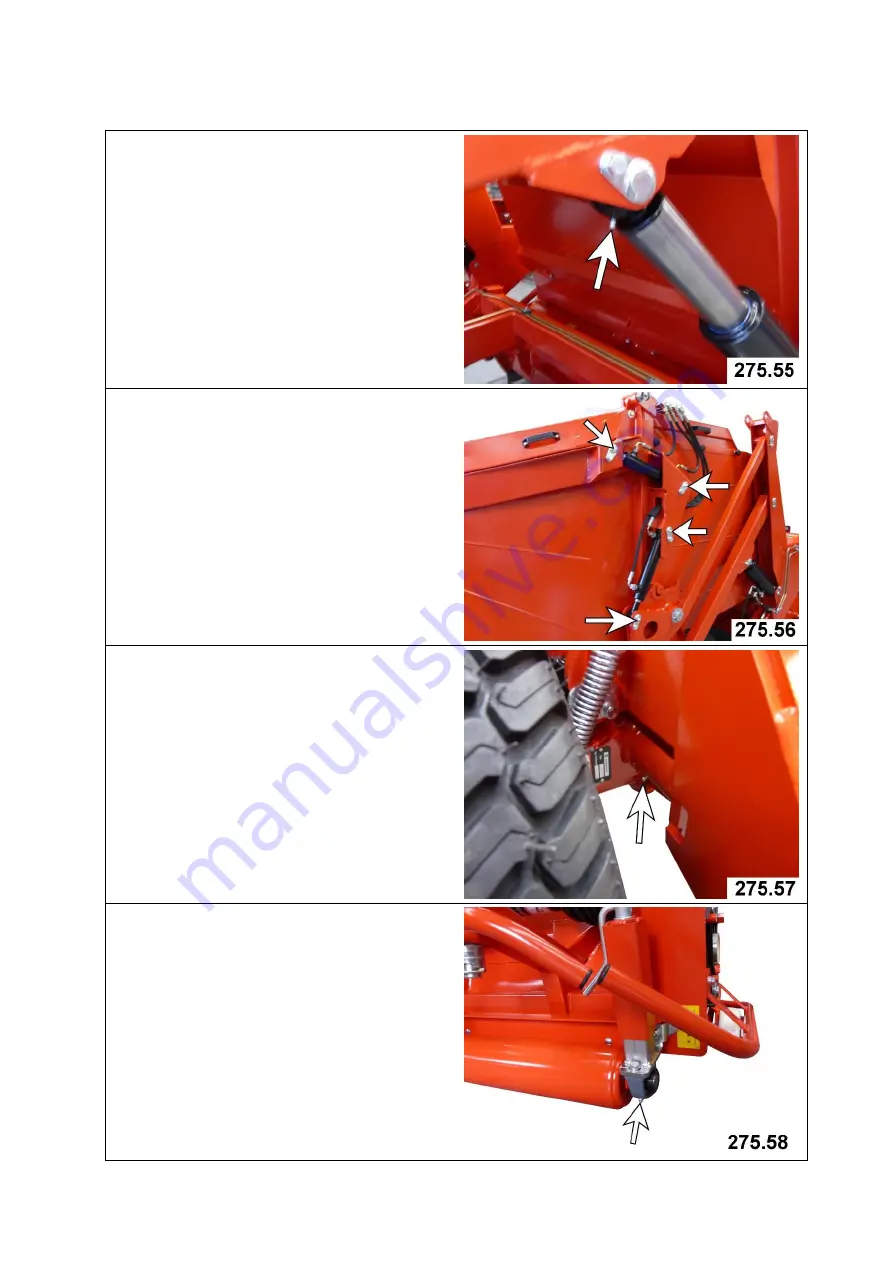
8.4. Lubricating points 

8.4.5. Discharging the hopper 

Bearing pins of hydraulic 
cylinders on right and left 


8.4.6. Discharging the hopper 

Joint of telescopic cylinder 


8.4.7. Pivot axle 

Bearing bush 


8.4.8

Front roller 

pedestal bearing unit left 


Summary of Contents for Super 600

Page 1: ...Translation of original operating instructions Lawn Maintenance Machine Super 600 275 001 From machine ID no 10102750005142001 Version May 2014 275 99 09...

Page 2: ...ll information illustrations and specifications in this manual are based on the latest information available at the time of publication We reserve the right to make changes at any time without notice...

Page 3: ...ll information illustrations and specifications in this manual are based on the latest information available at the time of publication We reserve the right to make changes at any time without notice...

Page 4: ...for conventional maintenance of lawns INTENDED USE This includes following tasks Gathering and collecting grass debris leaves and twigs Mowing lawns parks recreational areas golf courses extensively...

Page 5: ...nel 26 3 6 Installing optional anti scalp rollers 27 3 7 Installing optional golf course kit 28 29 3 8 Installing optional super contour kit 29 30 4 0 Attaching to a tractor 31 33 4 1 General informat...

Page 6: ...3 8 5 Clean channel 54 8 6 Lubricating points 55 8 7 Gearbox 55 8 8 Replacing ribbed V belt 56 57 8 9 Hydraulic system 58 8 10 Hydraulic connection diagram 59 8 11 Tool change at multi cultivation rai...

Page 7: ...SAFETY INSTRUCTIONS Carefully read all safety messages in this manual and warning signs on your machine Keep warning signs in good condition Replace missing or damaged warning signs Make sure that new...

Page 8: ...th the machine Prolonged exposure to loud noise can cause impairment or loss of hearing Wear a suitable hearing protective device such as earplugs to protect against objectionable or uncomfortably lou...

Page 9: ...before making adjustments connections or cleaning out PTO driven equipment Avoid high pressure fluids High pressure fluids which leak under high pressure can penetrate the skin and cause serious inju...

Page 10: ...tion in traffic Use headlights flashing warning lights and turn signals day and night Follow local regulations for equipment lighting and marking Always keep the safety devices in good condition Repla...

Page 11: ...tially toxic fumes and dust Hazardous fumes can be generated when paint is heated by welding soldering or using a torch Do all work outside or in a well ventilated area Dispose of paint and solvent pr...

Page 12: ...ate potential danger The hazard is identified by an exclamation point in a warning triangle An adjacent symbol shows information on how to avoid personal injury These safety signs their placement on t...

Page 13: ...ndstill 275 03 Tools for the multifunction head Never operate the multifunction head when the container is elevated There is danger of injury from the spinning tool drum and from parts flung out of it...

Page 14: ...s where there is a danger of crushing while parts could still be moving 275 07 Hopper flap opening When the tractor engine is running keep clear of the swivel area of the safety catch 275 08 Screen an...

Page 15: ...is not impaired Keep all persons clear of the danger zone of the machine Only attach the machine when the engine is at a standstill and the P T O drive is switched off Only use the cardan shaft alloca...

Page 16: ...to great danger Serious injury by moving parts can result The positions of the safety equipment on your machine A Protection device for cardan shaft connection can only be undone with tools B hoop gu...

Page 17: ...ithout notice 17 1 0 Safety Measures 1 3 Safety Equipment 1 3 2 at the remote control ATTENTION DANGER Lifting multi maintenance head Otherwise you expose yourself and others to extreme danger Serious...

Page 18: ...nly use a forklift with sufficient load carrying capacity Keep well clear of hoisted loads If the load falls it may cause fatal injuries Improper transport and assembly of the turf care machine may in...

Page 19: ...care machine is still fastened to the shipping frame move the forks into the shipping frame note direction of approach carefully raise the shipping frame unload the turf care machine from the shipping...

Page 20: ...ke changes at any time without notice 20 2 0 Transport 2 2 Transporting the Super 600 2 2 3 Hitching point for transport on a trailer Point C 2 items on the drawbar left arrow or a hole in the clips o...

Page 21: ...at any time without notice 21 2 0 Transport 2 2 Transporting the Super 600 2 2 4 Shipping frame The catcher A and drawbar B are not mounted for shipping The catcher A is fastened to the front of the...

Page 22: ...the container against accidental lowering For this work please use your personal protective equipment PSA such as gloves goggles ear protectors Attachment must be carried out on solid flat ground onl...

Page 23: ...Assembly 3 3 Mounting the catcher At least two persons are required for this work Remove the upper and side parts of the shipping frame Remove drawbar A from shipping frame Attach catcher to the two r...

Page 24: ...ng the catcher Move the attached catcher carefully to the back of the Super 600 Remove the bearing pin E for holding the catcher Remove the bearing pin F for holding the hydraulic cylinder G Move catc...

Page 25: ...socket A at a suitable location near the driver s seat Attach cable B from the battery to the 3 pin socket A Connect flat plug C of cable 1 to socket A at position D Connect flat plug E of cable 2 to...

Page 26: ...tice 26 3 0 Assembly 3 5 Connection of control panel The control panel has a 4 pin connector on the back into which the connector cable A must be plugged The control panel must be in a suitable bracke...

Page 27: ...anti scalp rollers ensure that only the verticutting blades touch the ground and not the fly regulators Setting anti scalp rollers NOTE Make the same anti scalp roller setting on both sides Release u...

Page 28: ...rew the front roller to the bores in the fixture plates on the left A and right not shown of the machine Use 3 hexagonal screws B with matching washers and nuts each on the right and left side The saf...

Page 29: ...ockwise The multifunction head is lowered Turn the cranks anti clockwise The multifunction head is raised Use the scale on the left B and right not shown to set the working height identically on both...

Page 30: ...secure the container against accidental lowering Position the divided trailing roller D between the multi cultivation rail and moving gear The trailing roller is bolted to the top holes of the clips o...

Page 31: ...irm and even ground DANGER OF TILTING Only attach the machine when the engine is at a standstill and the P T O drive is switched off The warning and information signs on the machine provide important...

Page 32: ...ening each drawbar Fasten the drawbar to the tractor and secure it Swivel the support upwards and check whether the hitched machine stands up straight Check whether the drawbar fits the tractor if you...

Page 33: ...y time without notice 33 4 0 Attachment to tractor 4 4 Adjusting the pto shaft To adjust the length hold the two shaft parts side by side within the shortest operating position and mark them Cut off t...

Page 34: ...tched off Never detach the machine when the container is elevated Only detach the machine from the tractor when it is empty 5 2 Detaching Lower the multi maintenance head to the ground Switch off the...

Page 35: ...for which the machine is set Grease the universal shaft see Operating Instructions for the universal shaft The warning and information signs on the machine provide important information for safe oper...

Page 36: ...ers in the wheel holders on the multi maintenance head and lock with spring clips Observe the following when setting the working height Observe irregularities of terrain bumps Note the degree of wear...

Page 37: ...ttle power from the battery All valves are closed when the controller is switched off Three modes can be selected at the control panel corresponding to the three functions of the turf care machine For...

Page 38: ...or vacuuming and collecting grass debris leaves and small twigs Tool set for verticutting with a tool spacing of 2 25 in Verticutting with a tool spacing of 2 25 in for year round relatively gentle ve...

Page 39: ...and ground conditions Special care should be taken when working and turning on a slope To empty the hopper the multi maintenance head must always be raised Observe irregularities of terrain bumps 7 2...

Page 40: ...ce 40 7 0 Operation 7 3 Start up Observe the following sequence during start up Drive onto the surface that is to be treated Press key 3b to switch on the control panel Lower the multi maintenance hea...

Page 41: ...ithout high level tipping NOTE the catcher can only be opened if the maintenance head is fully raised and display 1 is green Press key 3b to switch on the control panel It is emptied in Mode 7 Catcher...

Page 42: ...with high level tipping NOTE the hopper can only be lifted and emptied if the maintenance head is fully raised and display 1 is green Press key 3b to switch on the control panel The hopper is lifted i...

Page 43: ...tenance head is fully raised and display 1 is green It is emptied in Mode 7 Catcher open close Key 2 Unlock Key 7b catcher open close Actuate the control valve on the tractor to open the catcher Drive...

Page 44: ...Lift the safety cover A up to the stop Clean all screen surfaces ATTENTION Always clean the machine with a cloth or water never with your bare hands RISK OF INJURY NOTE Only clean grid plates allow th...

Page 45: ...tools Material is being collected poorly or not at all during verticutting Verticutting knives have been shortened by wear Replace tools the verticutting knives Verticutting knives have been worn down...

Page 46: ...the P T O shaft off when driving round tight bends Different tire pressure at wheels Check the air pressure and correct if necessary Different adjustment of jockey wheels or front roller Check adjustm...

Page 47: ...Wiedenmann have neither been tested nor approved by Wiedenmann The installation and or employment of such products can in some circumstances therefore have negative structural effects on your vehicle...

Page 48: ...bdenum disulphide 8 3 Maintenance and inspection list Machine in general Area Maintenance measure Maintenance interval Entire machine Clean the machine after use to ensure faultless functioning during...

Page 49: ...ange roller bearing see 8 4 1 and 8 4 2 100 hrs Front supporting rollers Lubricate the guide bushing of the height adjustment see 8 4 3 100 hrs Lubricate the wheel bearing see 8 4 4 100 hrs Check the...

Page 50: ...8 0 Service 8 3 Maintenance and inspection list Bogeys Area Maintenance measure Maintenance interval Quadruple swing bogey Lubricate the brass bushings of the swing units see 8 4 7 100 hrs Check the a...

Page 51: ...t to make changes at any time without notice 51 8 0 Service 8 4 Lubricating points 8 4 1 Multifunction head Left outer flange roller bearing A Upper drive flange roller bearing B 8 4 2 Multifunction h...

Page 52: ...lication We reserve the right to make changes at any time without notice 52 8 0 Service 8 4 Lubricating points 8 4 5 Discharging the hopper Bearing pins of hydraulic cylinders on right and left 8 4 6...

Page 53: ...eserve the right to make changes at any time without notice 53 8 0 Service 8 4 Lubricating points 8 4 9 Front roller pedestal bearing unit right 8 4 10 Cardan shaft Lubricate the outer slide profile i...

Page 54: ...secured against accidental starting Close the safety valves at both telescope cylinders to secure the container against accidental lowering Remove universal shaft from tractor and set aside Raise the...

Page 55: ...nd wait for all moving parts to come to a standstill The drive protection must be removed for maintenance on the drive of the sweeping head or multifunction head Loosen the three screws A and remove R...

Page 56: ...achine is attached to a tractor The tractor must be switched off and secured against being switched on accidentally Remove the drive protection A see 6 4 Loosen the hexagonal nut B and unscrew until t...

Page 57: ...threaded pins manually Generally align the ribbed belt pulley F to the ribbed belt pulley J with the aid of straight edge Tighten the threaded pins tight enough so the ribbed belt pulley can be align...

Page 58: ...e carried out by suitably trained personnel Fluids suddenly released under pressure can penetrate the skin causing serious injury For this reason always depressurize the system before disconnecting li...

Page 59: ...d specifications in this manual are based on the latest information available at the time of publication We reserve the right to make changes at any time without notice 59 8 0 Service 8 10 Hydraulic c...

Page 60: ...the safety valves at both telescope cylinders to secure the container against accidental lowering Remove universal shaft from tractor and set aside Raise the container completely Close the safety val...

Page 61: ...ribe the possible division of the tools The illustrations show the view from above through the service flaps B onto the tool drum D of the multi cultivation rail After the tool change ensure that all...

Page 62: ...division Flail mower blades Flail mowing fully mounted 100 Collecting A First and outer tool bracket left side not equipped B Double row 1 C Wind paddle double row not shown D Double row 2 E Double r...

Page 63: ...acing of 749 in and simultaneous mowing Collecting A First and outer tool bracket left side without cutting blades B Double row 1 C Wind paddle double row not shown D Double row 2 E Tool spacing 749 i...

Page 64: ...n and simultaneous mowing Collecting A First and outer tool bracket left side without cutting blades B Double row 1 C Wind paddle double row not shown D Double row 2 only cutting blades E Tool spacing...

Page 65: ...ol spacing of 2 25 in and simultaneous mowing Collecting A First and outer tool bracket left side without cutting blades B Double row 1 C Wind paddle double row not shown D Double row 2 E Tool spacing...

Page 66: ...ipment Always maintain the specified tire pressure Never inflate tires above the recommended pressure Do not heat wheels or tires or carry out welding work on them Heating tires may cause them to burs...

Page 67: ...one Disassembly for Disposal Place the machine on firm ground Drain the hydraulic oil and collect it in a suitable vessel Disassemble the machine from top to bottom IMPORTANT Strictly observe the regu...

Page 68: ...ges at any time without notice 68 9 0 Equipment 9 1 Equipment supplied Lawn maintenance machine Super 600 Attachment parts drawbar Connectors for power supply Control panel matching suction cup holder...

Page 69: ...ns in this manual are based on the latest information available at the time of publication We reserve the right to make changes at any time without notice 69 9 0 Equipment 9 2 Optional equipment Super...

Page 70: ...1 Max drive speed 1 min 540 2 Working speed multifunction head 1 min 2600 3 Min power required for tractor HP KW 50 38 4 Min hydraulic operating pressure psi 2538 5 Max hydraulic operating pressure p...

Page 71: ...ecifications in this manual are based on the latest information available at the time of publication We reserve the right to make changes at any time without notice 71 10 0 Specifications 10 1 Technic...

Page 72: ...1350 1000 M27 490 360 625 450 950 700 1200 875 1350 1000 1700 1250 1600 1150 2000 1500 M30 675 490 850 625 1300 950 1650 1200 1850 1350 2300 1700 2150 1600 2700 2000 M33 900 675 1150 850 1750 1300 22...

Page 73: ...ke changes at any time without notice 73 10 0 Specifications 10 3 Serial Number Record product identification No serial no in the space provided below Always quote this number when ordering spare part...

Reviews: