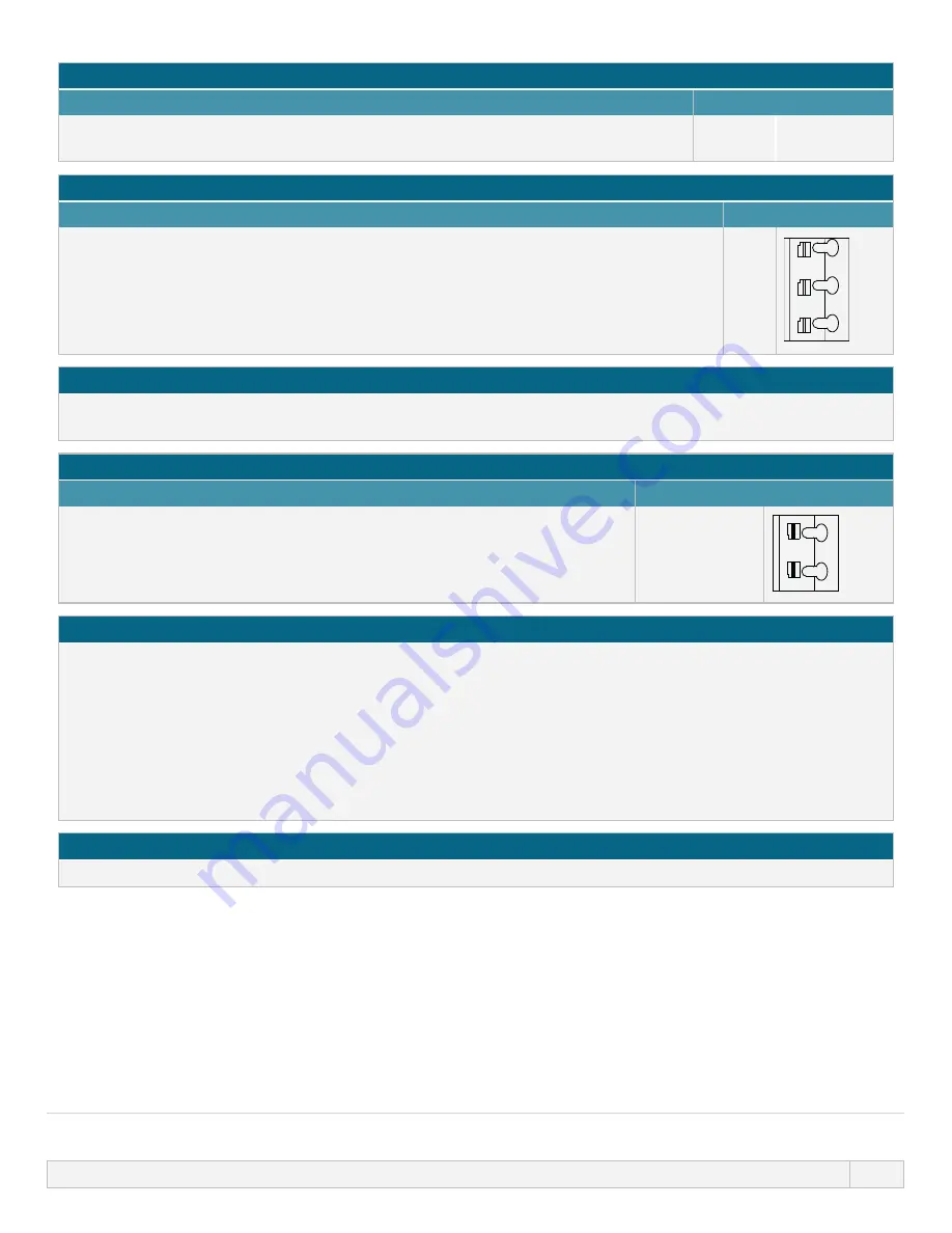
General Alarm output (J2)
RLY1
The default for Relay 1 is General Alarm, on Un models this output (1) can be
configured in the control settings menu.
Table 15 – Run status output (J2)
RLY2
Connect the output device to the C (common) terminal of the relay connector and either
the N/C (normally closed) or N/O (normally open) terminal as required.
This relay coil is energised when the pump is running.
The default for output 2 is run status, on Un models this output (2) can be
configured in the control settings menu.
3.
N/C
2. C
1.
N/O
3
2
1
Table 16 – Output 3 and 4 (J1)
Two additional relay outputs are provided on the Unrelay model of the pump. These outputs are inactive
by default, the function of the output must be configured in the control settings menu.
Configurable remote stop or contact input (J8), 24 V logic input
Contact stop input
If Analog 4-20 mA mode is selected then terminal J8 will be configured as a
remote stop automatically.
If Contact mode is selected then the input J8 will be configured as a contact
input automatically.
J8
2. I/P
1. 5 V
2
1
Remote stop logic 24 VDC (J8)
Connect a remote switch between the Stop/Contact terminal and the 5 V terminal of the Run/Stop I/P connector
(J8). Alternatively a 5 V-24 V logic input may be applied to the Stop/Contact terminal, ground to the GND terminal
of the adjacent 4-20 mA I/P connector (J3 or J4).
PLC 24 V relay/solenoid driver outputs are not suitable due to the high input impedance of the Stop/Contact
terminal.
The sense of remote stop input can be configured in software using control settings menu.
Remote stop is operational in manual and analog mode.
Contact
To operate the pump in contact mode the remote stop input must be set to "High".
13 INSTALLATION: PART 4 (CONTROL CONNECTIONS AND WIRING)
94


