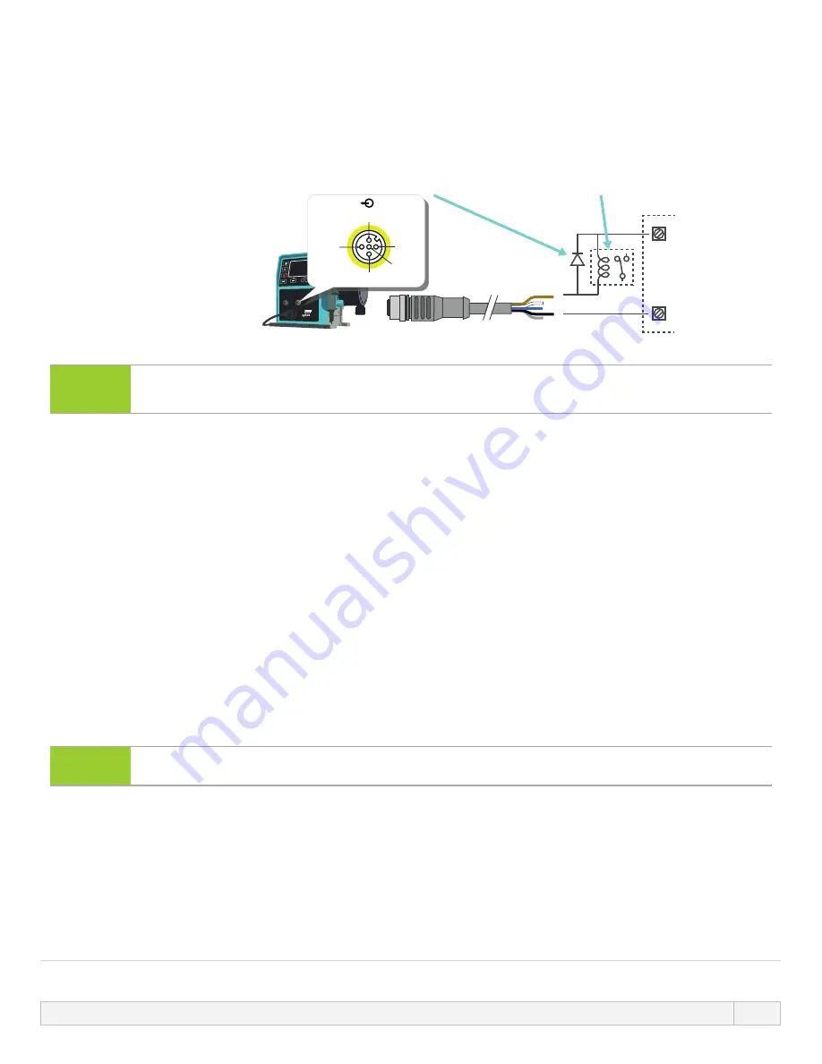
External relay (Only applies to Pin 1 and Pin 2)
Example wiring for an external relay, the N/O or N/C contacts could be used for any device.
The relay in the illustration below needs to be sized correctly for the application to prevent damage to the pump
transistors.
Diode
Relay coil
1 A 100V
2k2 Typical / 1k2 Minimum
PLC
1
4
1
2
3
4
5
+24V DC
Common
NOTE28
Diagram depicts Run Status output. The Alarm output must be wired in the same way except using
the white wire from pin 2 instead of the brown wire from pin 1.
Alarm output
Pin 2, Output 1
This example requires external 24 V power for control. If connecting to a PLC, 24 V is usually available Alarm
conditions are generated by system errors or leak detection.
Run Status Output
Pin 1, Output 2
This example requires external 24 V power for control. If connecting to a PLC, 24 V is usually available. This output
changes state when the motor starts/stops.
Speed: Analog output (Models: Remote, Un)
An analog signal current within the range 4-20 mA into 250 Ω is available between pin three and pin four of the
output connector. The current is directly proportional to the pumphead rotation speed. 4 mA = zero speed; 20 mA
= maximum speed.
On the Un version there is also an option to match the scale of the 4-20 mA input if this has been
reconfigured by the user. This option is available in the Control settings menu.
NOTE29
If the mA output is to be used for reading from a multimeter, a 250 Ω resistor is required in series.
13 INSTALLATION: PART 4 (CONTROL CONNECTIONS AND WIRING)
91


