Page 38
VP-X Installation and Operating Manual
Rev. D (August 5, 2020)
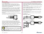
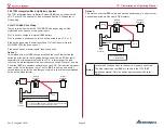
5.19a Pitch Trim Wiring
The trim wires are grouped together by trim function, and shown on the Load
Planning worksheet. They are separated from each other by number, but are
physically located next to each other on the connector. Each trim servo has
five wires: two for motor power, and three for position feedback.
Pitch Trim
Function
VP-X Pin
I/O
+2.5 reference voltage (wht/blu)
J1-8
O
Ground (wht/org)
J1-9
--
Position feedback (wht/grn)
J1-10
I
Trim motor (wht)
J1-11 (connect either way)
O
Trim motor (wht)
J1-12 (connect either way)
O
Pitch Trim Up switch input
J2-18
I
Pitch Trim Down switch input
J2-19
I
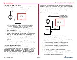
Connect the wires for the pitch trim system as follows, if installed:
•
Run the 5-conductor wire (five wires bundles together) to the trim
motor. The colors on the wiring harness match the colors on a Ray
Allen sensor and can be connected color to color.
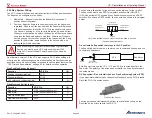
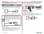
Note: in some aircraft, it is desirable to provide a connector near the
elevator trim servo. A popular method is to crimp d-sub connector
terminals (machined barrel, mil-spec) to the servo wires and to the
wiring harness. First, slip a piece of large heat shrink tubing over the
wiring harness and move aside for later. Then, connect the terminals
on each wire pair and seal with heat shrink tubing, which insulates as
well as provides a secure connection. Be sure to offset each terminal
so that the bundle doesn’t get too big. Cover the bundle of wires with
the large heat shrink tubing.
• Connect the switch input pins to the trim switch (pilot and co-pilot).
Connect the other side of the switch to ground.
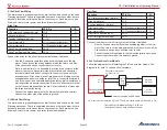
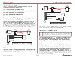
5.19b Roll Trim Wiring
The trim wires are grouped together by trim function, and shown on the Load
Planning worksheet. They are separated from each other by number, but are
physically located next to each other on the connector. Each trim servo has
five wires: two for motor power, and three for position feedback.
Roll Trim
Function
VP-X Pin
I/O
+2.5 reference voltage (wht/blu)
J1-3
O
Ground (wht/org)
J1-4
--
Position feedback (wht/grn)
J1-5
I
Trim motor (wht)
J1-6 (connect either way)
O
Trim motor (wht)
J1-7 (connect either way)
O
Roll Trim Left switch input
J2-16
I
Roll Trim Right switch input
J2-17
I
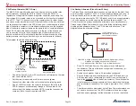
Connect the wires for the roll trim system as follows, if installed:
•
Run the 5-conductor wire (five wires bundled together) to the trim
motor. The colors on the wiring harness match the colors on a Ray
Allen sensor and can be connected color to color.
• Connect the switch input pins to the trim switch (pilot and co-pilot).
Connect the other side of the switch to ground.
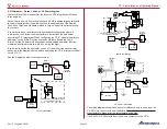
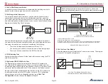
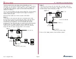
5.19c TruTrak Auto Trim Module
Follow the diagram below if installing the TruTrak auto trim module. The
diagram is for both 14 volt and 28 volt systems.
Ray Allen
Trim Servo
TruTrak
Pitch Servo
VP-X contols pitch trim when AP is off, TT auto trim controls pitch trim when AP is ON.
Pitch trim motor power
J1, pins 11 & 12
8
11
J1-11
J1-12
13
1
12
Autopilot power
out (5 amp)
Power to roll servo and AP head
10
9
VP-X
TruTrak
Auto
Trim
white
white
TruTrak Auto Trim Module Wiring 14 & 28 volt
Other connections on each device not shown.


