Page 50
VP-X Installation and Operating Manual
Rev. D (August 5, 2020)
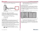
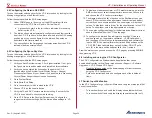
5.25b TCW IBBS 3/6ah Wiring
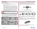
There are two ways to wire the TCW IBBS 3/6ah, depending on if the
protected device has one or two power inputs.
Pin 5 is used to charge the internal IBBS battery.
Pin 6, 7, 8 are used as power source for the devices wired to pins 12-15.
If the device has a single power input use option 1.
If the device has dual power inputs use option 2.
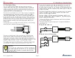
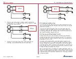
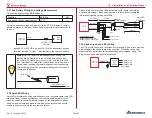
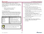
Option 1:
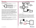
This method wires the IBBS charge circuit and the circuit that carries the
device load (the device that is getting backup power like an EFIS or radio)
separately from two separate pins on the VP-X. In this manner the load
circuit can be protected separately from the charge circuit. Wire pin 5 and
pins 6, 7, 8 from the IBBS into separate power pins on the VP-X (pins 6, 7, 8
can use one VP-X pin to conserve outputs if the backed up devices fit within
the CB limit). Set the circuit breaker value for the circuit that goes to pin 5 on
the IBBS to 5 amps, and set the circuit breaker value(s) for the wire(s) that go
to pins 6, 7, 8 to the value recommended by the device manufacturer.
+
-
Batt
Pin 5 powers IBBS charging circuit set to 5A breaker value.
Pins 6, 7, 8 powers load only. Set CB value for load.
VP-X
IBBS
15 Pin
DSub
5
6
7
8
12
13
14
15
Starter
Contactor
Battery
Contactor
Set for CB Value
To Device(s)
5A
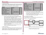
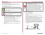
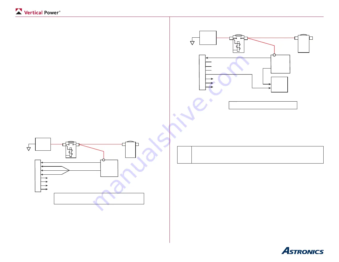
Option 2:
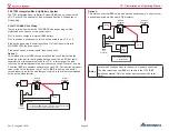
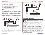
This method uses the IBBS solely as a backup power supply to a device that
has dual power inputs (like most EFIS displays). Wire per the diagram and
see IBBS instructions for further detail.
+
-
Batt
See IBBS instructions for further details.
VP-X
IBBS
15 Pin
DSub
5
6
7
8
12
13
14
15
Starter
Contactor
Battery
Contactor
To Device(s)
5A
Not Used
EFIS
Pri Pwr
BU Pwr
Note: The other pinouts on the IBBS are shown in the TCW IBBS installation
manual. Only the power inputs are shown here for clarity.
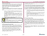
5.26 Dual Battery/Single Bus Wiring
Note
The Primary Power System (PPS) is a single battery unit only, so
the following section applies to traditional systems only. The PPS is
fully compatible with dual alternators.
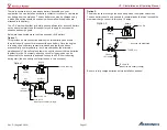
Some installations require the use of a dual battery architecture. Commonly
this is used for dual Lightspeed ignitions or engines with an electric ECU
like a Viking, Subaru or Chevy. Sometimes an additional battery is used to
keep the EFIS alive during start (Option 2 is the easiest way to wire for this
scenario).
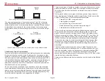
While there are many variables to consider, we generally recommend
installing a backup alternator instead of a second battery if extending the
length of time for backup power is a design goal. The main reason is that a
backup alternator allows you to fly indefinitely (assuming the electrical load
is less than the backup alternator capacity which is easy to do with modern
avionics) while a second battery only has limited endurance. While the
backup alternator costs more initially than a second battery, it likely requires
less ongoing maintenance (the aux battery should be replaced every two
years) and better fits the stated goal of longer electrical system endurance in
case of primary alternator failure.

