Page 58
VP-X Installation and Operating Manual
Rev. D (August 5, 2020)
6.11
Wig-Wag Configuration
In the VP-X Configurator, go to Wig Wag Configuration.
XeVision HID light customers: The VP-X includes a license to use the
patented XeVision warm up and pulsing algorithms and therefore the VP-X
wig wag will not void the XeVision warranty. Set the warm-up period to 30
seconds for XeVision HID lights.
Note
If your lights have a built in wig-wag circuit, use the functionality in
the VP-X. The wig-wag in the VP-X has many advanced features
and is designed to work as part of the overall system. We do not
recommend using an external wig-wag system. Typically, there is
a second power pin, a sync wire, and/or a master/slave wire, all of
which should not be wired. Wire only the primary power wire and
ground wire on each light.
Wig wag on the VP-X is activated automatically when the lights are on and
the aircraft is above the specified airspeed. There is
not a dedicated wig-wag
switch.
A pin used for wig wag cannot be set to always off, always on or as the
secondary alternator.
Do the following to configure wig-wag:
• Set the warm-up delay. A 5-second delay minimum is required to
detect no-current or over-current conditions. We recommend a
minimum 30 second warm up period for HID lights. Check with your
manufacturer for specific timing.
• Set the indicated airspeed above which the devices will wig-wag. If
the lights are turned on below that speed, they will be steady, then
wig wag automatically above that speed. If this is set to 0 the pin or
pins will always wig wag when turned on (this is primarily so you can
test the wig wag feature during the build process).
• Select one or two power pins to wig wag. If only one power pin is
selected, it must be assigned to the pin #1 wig wag slot. Set both
pins to Disable to disable the wig-wag feature.
NOTE
: The pin must be assigned to a switch prior to enabling it for
wig-wag.
6.12
Trim Configuration
In the VP-X Configurator, go to Pitch Trim Configuration. Follow the
instructions below and repeat for roll trim.
You can run the trim from both a trim switch as well as from the VP-X
Configurator.
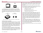
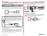
The position sensor range is 0 to 255. The limits are set numerically based
on actual feedback from your sensor. Below is a diagram showing what some
typical limits may be:
Trim Up Limit
Trim Neutral
Trim Down Limit
220
100
30
Trim Up Limit
Trim Neutral
Trim Down Limit
30
150
220
Depending on your installation the up limit, for example, may be a high
number or a low number. The actual number is irrelevant – it simply refers to
a trim position.
The Ray Allen trim servos automatically stop at the mechanical limits of
travel.
Each of the two trim setup pages is similar. Repeat the following for both the
pitch and roll trim.
Verify that each trim switch is in the neutral (middle) position,
and that the area around the trim motor/tabs is clear before
starting configuration.
When operating the trim motor for the first time, carefully check
that airframe components don’t bind or bend under the motor
load.


