Page 15
VP-X Installation and Operating Manual
Rev. D (August 5, 2020)
VP-X
SPST
Switch
(ON)
To Gnd
Power
In
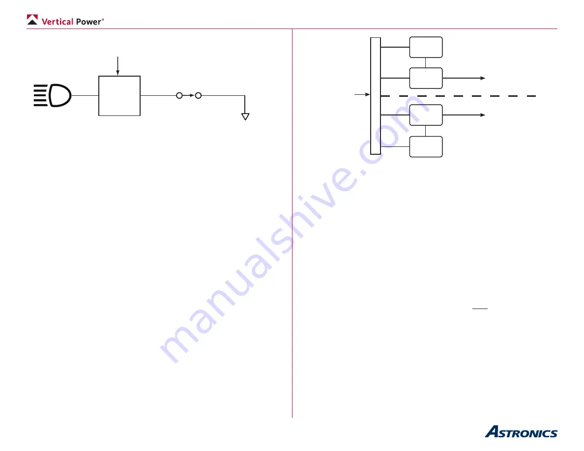
Above, switch is closed so lamp is on.
Here you can see that the light turns on when the switch is closed, and the
actual power switching is done inside the VP-X and not by the switch. The
switch simply tells the microprocessor to turn on the device(s) associated
with the switch.
Note that the starter circuit and master switch circuit are different and
explained elsewhere in this manual.
4.3 Wiring Harness
A VP-X wiring harness is available to simplify the installation of electrical
system. Appendix B at the end of this manual details the contents of the
wiring harness kit.
4.4
Dual Bank Technology (VP-X Pro)
The VP-X Pro includes our Dual Bank technology that has two independent
power banks in a single system, delivering unprecedented levels of
redundancy and safety. Builders can now easily divide avionics and other
electrical loads between two power banks, and should one bank controller
fail the other bank will continue to operate independently and be able to
provide power to the starter contactor. Each bank of circuits is powered by an
independent power supply and microprocessor.
Power
Supply A
ECB
Bank A
ECB
Bank B
Power
Supply B
Bank A
Power Circuits
Bank B
Power Circuits
Power In
Overview of Dual Bank Technology
The power pins associated with each bank are shown in Appendix A.
It is important to understand the following:
• Each switch input (1 through 10) can be read by either
microprocessor. Devices on both bank A and bank B can be
controlled by a single switch input. For example, the landing light
switch can control BOTH the left light (wired to bank A) and the right
light (wired to bank B).
• The two banks do not share common components on the circuit
board – each bank is isolated from the other outside of the main
power bus (input) and ground.
• Either bank (A or B) can power the starter circuit. Therefore if a bank
fails you can still start the engine.
• Pitch trim is controlled by both processors. Both processors must
agree to run the pitch trim before it can run. Therefore, if either bank
fails the pitch trim cannot operate.
• The roll trim is powered by bank A.
•
The flaps are controlled by bank B.
• The serial and Ethernet lines are connected to the bank A
microprocessor. If bank A fails then communications with the EFIS
are lost. In this case, bank B will continue to operate normally but
you will not receive status on the EFIS.
•
Bank A provides the reference voltage to the trim and flap indictors.


