Page 39
VP-X Installation and Operating Manual
Rev. D (August 5, 2020)
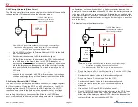
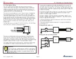
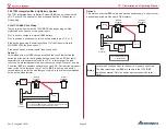
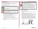
5.19d Co-Pilot Disconnect Switch
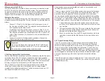
A co-pilot disconnect function can be implemented by installing a switch to
disconnect the common ground wire to the co-pilot stick.
5.19e Wiring a third trim motor
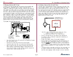
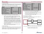
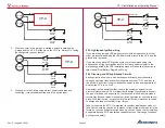
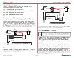
If you want to control a third trim motor, you can wire the third motor in a
conventional manner and source circuit-protected power from one of the
VP-X power pins (set circuit breaker value to 1A for this circuit). The diagram
below shows a generic implementation, or you can use the switch and wiring
diagram provided by Ray Allen Company.
Trim
Motor
Power pin
VP-X
(on)-off-(on)
DPDT Switch
Note the above diagram is for a single switch. The complexity increases if
you want to wire a pilot and co-pilot switch as well. In deciding which axis to
wire using this method, we recommend considering the following:
• There is no third-axis position indicator with the VP-X.
• You have only one switch to control this axis to keep wiring simple
• There is no backup control from the EFIS for this axis
5.19f PH Aviation Trim
Contact Vertical Power Support for the latest information on using the VP-X
with PH Aviation Trim.
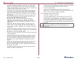
5.19g Garmin GSA 28 With Auto-Trim
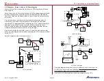
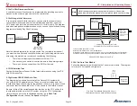
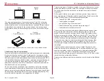
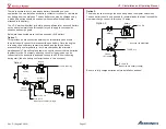
The diagram below shows how to install the Garmin G3X system with
one or two GSA 28 autopilot servos. These servos also include auto trim
functionality. Repeat this wiring for the pitch and roll servo. If you have a third
yaw servo, that is wired outside the VP-X as shown in the Garmin manual.
Be sure to turn off the variable speed trim function on the VP-X unit as this
functionality is included in the G3X system. Using the VP-X Configurator
(later, when you get to the configuration section), go to
Pitch Trim
Configuration
section, then set the
Speed
setting to 0.
Note
Not all wiring to complete each module is shown. Consult the
respective installation manuals for complete details on other wiring.
Ray Allen
Pitch or Roll
Trim Motor
T2-7/12, T3-12
or equiv
VP-X
J1
Pitch
WHT
WHT
Garmin GSA 28
Pitch or Roll
Autopilot Servo
Carefully strip sheathing from wires.
Cut white wires only and connect to GSA 28.
Turn off variable speed trim on VP-X.
Details for non-white wires in VP-X Install Manual.
Orientation of white wires does not matter to VP-X, and can be changed using the configurator.
Consult Garmin manual for correct orientation of white wires between GSA 28 and trim motor.
13
14
11
12
11
12
8
9
10
Roll
6
7
3
4
5
Wiring GSA 28 Servos to the VP-X.
5.19h Trio Auto Trim Module
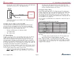
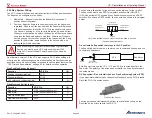
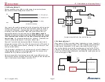
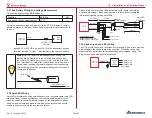
Follow the diagram below if installing the Trio auto trim module. The diagram
is for both 14 volt and 28 volt systems.
Trim Dn J2-15
Trim Up J2-14
J12-6 B
J12-5 A
Signal
Voltage
Polarities
(-) + (-)
(-) (-) +
At Rest
Trim Up
Trim Dn
Stick Switches
VP-X
Ray Allen
Trim Motor
Trio Auto Trim Module Wiring 14 & 28 volt
Other connections on each device not shown.


