Page 37
VP-X Installation and Operating Manual
Rev. D (August 5, 2020)
5.19 Trim System Wiring
The VP-X controls the trim motor as well as provides the circuitry to
report the trim position to the EFIS. It also handles runway or faulted trim
conditions, and enables the EFIS to control the trim from the screen. All
of the trim wiring is connected directly to the VP-X, and the trim position is
reported to the EFIS over the serial data line.
The trim motor circuit breakers are set at 1 amp, and are not configurable.
Most experimental aircraft use trim servos from the Ray Allen Company
(http://www.rayallencompany.com). These servos are self-contained units
that include the trim motor as well as a position sensor. These servos are
designed to run at 14 volts, and the VP-X Pro provides regulated 14v power
to the trim motors so they can operate safely in 14v or 28v systems. The
general principles described in this section apply to other brands of trim
motor as well.
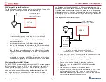
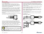
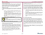
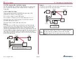
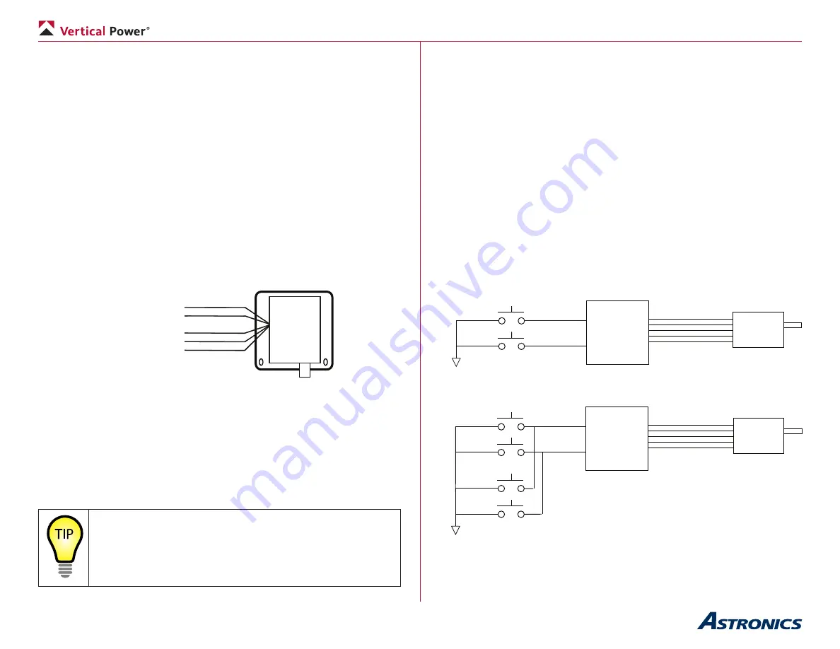
The Ray Allen trim servo (models T2-7A-TS, T2-10A-TS, or T3-12A-TS) has
five 26 AWG wires, as shown in the diagram below:
Ray Allen
Trim Servo
White
White
White/green
White/orange
White/blue
The trim motor itself is driven by the two white wires. It does not matter
how they are connected, as the polarity can be changed using the VP-X
Configurator. The direction of travel is controlled by reversing the positive
and negative connections to the trim motor. This is done conventionally using
switches or relays, but is done in the VP-X with solid-state circuitry.
The position sensor connects with three wires – white/green, white/ orange,
and white/blue. The three wires are wired directly to J1 on the VP-X.
Important
:
Do not use the trim position inputs on the EFIS. The EFIS gets
trim position information from the VP-X over the serial data line.
No external relays or switches are required between the trim
servo and the VP-X.
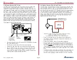
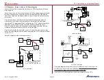
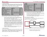
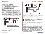
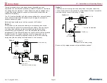
You can wire trim switches for the pilot and, optionally, for the co-pilot. The
trim switches must be momentary action so the trim motor runs only when
the button or lever is pressed. You can use either an SPST momentary action
button OFF-(ON) or an SPDT momentary action switch (ON)-OFF-(ON), with
a middle OFF position.
Each trim axis requires two input pins: one to command trim in one direction,
and one to command trim in the opposite direction. No external relays,
modules, or indicator lights are required.
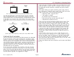
Ray Allen G205 and G207 stick grips should be wired per option 2 in the
Ray Allen installation manual (shown in “Appendix F – Ray Allen Stick Grip
Wiring” on page 80 of this manual.)
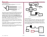
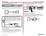
You may optionally wire a master trim disconnect switch in series between
the VP-X and the trim motor.
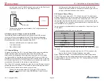
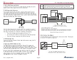
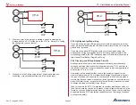
The diagram shows the general wiring layout. It is repeated identically for
both pitch and roll.
Wiring pilot trim switch only
Ground
Trim Up
Trim Dn
VP-X
Trim Motor
& Position
Sensor
Wiring pilot and co-pilot trim switches
Trim Up
Trim Dn
VP-X
Trim Motor
& Position
Sensor
PILOT
Ground
CO-PILOT


