Page 60
VP-X Installation and Operating Manual
Rev. D (August 5, 2020)
Motor
polarity
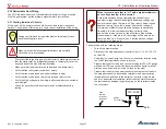
Standard/Inverted. Press the Up or Down buttons, and the
flaps should move in the appropriate direction. If not, change
the polarity until the flaps run in the correct direction. Press
Update
.
Once the motor direction is correct,
verify the flap switch
is wired correctly
by moving the flaps using the flap switch
(note: press
Update
button to save settings before using flap
switch)
Slow
Retract
When this feature is enabled, the flaps retract at
approximately 50% slower speed than normal while the
engine RPM is above
the configured RPM limit.
Flap Reflex Midpoint 1 must be set, and flaps must be set to “Position”
as described above. Midpoint 1 position should be set to the
neutral position, and UP should be set to the reflex position,
as described below. See
“10.5 Trim and flap operation”
more details.
Continuous
Flaps
Allows you to command a further flap down position before
the flaps reach the next stop. If enabled, you can bump the
flap down switch while the flaps are moving down and it will
continue to the next down position. Must be used with flaps in
“Position.”
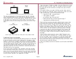
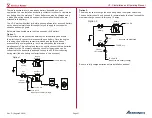
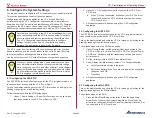
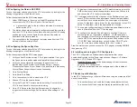
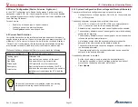
1. Read position here
2. Enter position here
Reading and Entering Flap Position on the VP-X Configurator
Note
The Up/Dn and midpoint limits only need to be set if a position
sensor is installed.
Up limit
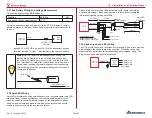
Run the flaps all the way up using the Up soft key. Note
the number that shows the flap position (should be on the
screen, between 0 and 255). We recommend setting it a few
numbers short of the actual limit to allow for position slop.
Midpoint 1/2
Allows you to set intermediate flap stops. These are disabled
when the flap control is set to Momentary. Disregard for now.
Note: if these are set to non-zero values, they must be in
numerical order consistent with the up and down limits or an
error occurs during save.
Down limit
Run the flaps all the way down (or the desired end point)
using the Down soft key. Note the number that shows the
flap position (shown on the screen, between 0 and 255). We
recommend setting it a few numbers short of the actual limit
to allow for position slop.
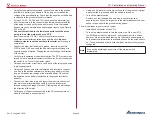
Note on up and down limits:
Make sure the limit value (the number 0 - 255 corresponding
to the position) is set before or at the point of the physical limit.
For example, if the down limit value is set to 0, but the furthest it
goes is down to 8, then it will never reach zero and continue to
drive the motor in anticipation of reaching zero. The flap circuit
will reach the max run time of 45 seconds and then the circuit
will fault.

