Page 28
VP-X Installation and Operating Manual
Rev. D (August 5, 2020)
Starter
Contactor
VP-X
J10-1
S
Starter
Switch
PPS
VP-X
J10-1
Starter
Switch
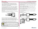
With the Primary Power System (PPS)
With a Convential Starter Contactor
Do not connect the battery until the system is wired and tested.
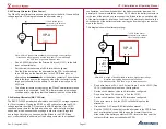
• Install an 18 AWG wire from J10-1 to the starter switch.
• Install an 18 AWG wire from the starter switch to the main battery
starter switch input pin on the circular connector on the PPS.
Alternatively, run an 18 AWG wire from the starter switch to the
“S” terminal on a conventional starter contactor, as shown in the
following image.
Power
Power
Coil gets ground from
mounting bracket.
“S” Terminal
Positive power from
Control Unit or starter
button activates coil
(closes contactor).
Some contactors have a
post on the flat surface.
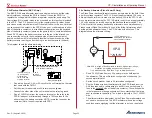
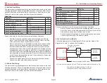
• Install a diode on the starter contactor coil as shown below. Note the
direction of the diode.
The starter contactor typically draws about 2 to 4 amps (depending on
model) at 14 volts. The VP-X can operate down to 6 volts, so it will not reboot
during normal engine starting. The VP-X does not boost voltage to any of the
devices it powers.
BAT
CTC
Starter
Use ring terminal to
fasten to mounting bolt (ground)
S
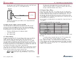
Disconnect the cable beteween the starter contactor and starter
until the electrical system is completely tested.
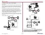
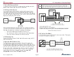
If you are installing an Aircraft Spruce keyed ignition switch A-510-2 or
similar, a drawing is provided below. It follows the same wiring as the
example above, but shows the keyed ignition switch instead of a generic
switch.
Starter
Contactor
ACS A-510-2
Ignition Switch
VP-X
J10-1
BATT
S
S
Starter wiring with a keyed ignition switch.


