Page 21
VP-X Installation and Operating Manual
Rev. D (August 5, 2020)
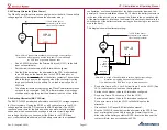
4.8a Over-voltage Planning
An over-voltage condition is initiated by a failure in either the voltage
regulator or the alternator which causes the voltage to rise above a safe level
for the avionics and other electrical equipment. Typically the over-voltage
level is set at 16.0 volts for a 14v system and 32.0 volts in a 28v system.
Over-voltage protection is provided by the VP-X, and therefore an external
device is not needed for this function. Over-voltage protection is provided by
removing power from the Field wire when the bus voltage exceeds a pre-set
limit for a pre-set period of time. If your system comes with an overvoltage
protection circuit, the VP-X system is compatible with “crowbar” type circuits.
These simply short the alternator field wire to ground, causing the field circuit
breaker to pop.
4.8b Low-voltage Planning
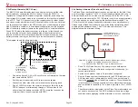
During flight, the normal bus voltage should be around 13.8 to 14.2 volts.
A low voltage condition is most likely due to one of the two following
circumstances:
1. The alternator has failed causing the bus voltage to drop from 14.2v
to 12.4 volts or less (double for a 28v system).
2. The electrical loads on the aircraft exceed the capacity of the
alternator, which is unable to keep the battery fully charged. The bus
voltage will slowly decline until the low voltage alarm is triggered.
The low voltage alarm may be provided through the EFIS.
4.9 Landing Light Wig-Wag (Pulsing) Considerations
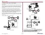
Various circuits can be configured to wig wag external lights. In order to flash
two different lights, they must each be wired to a separate pin on the VP-X.
Lights that are wired together to a single pin cannot be flashed separately
(although they can be flashed together). Wire each light that you want to
flash independently to separate pin.
In the setup menu, you specify which power pins you want to wig wag. It
then alternates power on those pins. For example, if you configure two lights,
a taxi light and a landing light, then those two pins will wig-wag or pulse.
Pulsing begins automatically above a specified airspeed so the lights are
always steady on the ground and pulsing when in the air. You can specify the
warm up time (5 secs to 60 secs), and the light is steady on for the specified
time period before pulsing.
Some LED landing lights include a built-in wig wag function. We recommend
using the wig wag built into the VP-X, which includes additional features and
also simplifies wiring.
4.10 HID Light Considerations
HID lights draw about double their normal power during the first 30 seconds
or so of operation. Because of this, all HID lights must individually be
connected to a 10A circuit, set to a 10A breaker value.
4.11 Electronic Ignition Considerations
The VP-X can be used with various electronic ignitions (EI) as long as the
appropriate safety considerations are taken into account. Most EIs, such as
Lightspeed or E-mags, require external electrical power to operate. Others,
such as P-mags or Lasar, have internal backups and can operate with or
without external power. P-mags require external power for starting and idle.
Make sure that at least one ignition source is wired directly to
the battery as per the ignition manufacturer’s instructions if you
are running dual Els that require external power!
If at least one magneto or p-mag is installed, you can provide power to the
other ignition via the VP-X. Consider using some form of Backup Circuit to
provide power in case of multiple failures (failure of the magneto and failure
of the VP-X at the same time-unlikely but possible).
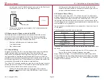
Some examples are shown below, and are meant to be guidelines only.
The builder is responsible for determining the appropriate level of
redundancy for his or her aircraft
:
• Dual Lightspeed or e-mag ignitions: wire one directly to the battery
(per manufacturer’s instructions) and one to the VP-X. Or, wire both
to the batteries per the ignition manufacturer’s diagram.
• One Lightspeed/e-mag and one magneto: wire the Lightspeed/e-mag
to the VP-X.
• Dual p-mags: wire both to the VP-X.
• One e-mag and one p-mag: wire both to the VP-X on individual
power pins.
• Dual magnetos: neither is wired to the VP-X, as they don’t require
external power.
• Lasar: Wire the Lasar power to the VP-X. The magnetos act as
backups.
• G3: Wire the G3 power to the VP-X. The magnetos act as backups.
• Rotax: has its own built-in alternator that is always on and wired
separately from the VP-X.
• Jabiru: has its own built-in alternator that is always on and wired
separately from the VP-X.


