45
11) Low Water Cut-off (may be required by local jurisdiction) – Protection of this boiler against low water and/or
inadequate flow is provided by the UL353 certified flow switch built into the boiler. This is a water tube boiler and
this flow switch is therefore the only effective way to provide such protection. Section HG614(c ) of the 2015
ASME boiler and Pressure Vessel Code recognizes the use of a listed flow switch in lieu of a low water cut-off on
water tube boilers.
In the event that a local jurisdiction insists upon the installation of a low water cut-off with this boiler, refer to Part X
and the low-water cut-off manufacturer’s instructions for proper wiring. Install the low water cut-off in the supply
piping at the point prescribed by the local jurisdiction (generally at a point above the boiler).
If a probe type low water cut-off is used, be certain that it is located at a point in the piping from which air can escape to an
automatic air vent. Generally, this means that there should be no down-turns in the piping between the low water cut-off and
the point where the automatic air vent is installed. Failure to do this may result in nuisance boiler shut-downs due to small
amounts of air trapped around the probe.
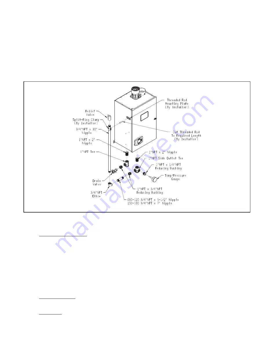
FIGURE 9.6: FACTORY SUPPLIED PIPING AND TRIM INSTALLATION
D. Piping for Special Situations
1) Systems containing oxygen - Many hydronic systems contain enough dissolved oxygen to cause severe corrosion
damage to a this boiler. Some examples include:
• Radiant systems that employ tubing without an oxygen barrier.
• Systems with routine additions of fresh water.
• Systems which are open to the atmosphere.
If the boiler is to be used in such a system, it must be separated from the oxygenated water being heated with a plate heat
exchanger. Consult the heat exchanger manufacturer for proper heat exchanger sizing as well as flow and temperature
requirements. All components on the oxygenated side of the heat exchanger, such as the pump and expansion tank, must be
designed for use in oxygenated water.
2) Piping with a Chiller - If the boiler is used in conjunction with a chiller, pipe the boiler and chiller in parallel. Use
isolation valves to prevent chilled water from entering the boiler.
3) Air Handlers
- Where the boiler is connected to air handlers through which refrigerated air passes, use flow control
valves in the boiler piping or other automatic means to prevent gravity circulation during the cooling cycle.
Summary of Contents for Shadow Series
Page 10: ...9 Figure 5 1 Wall Layout Mounting Hole Location...
Page 11: ...10 Figure 5 2 Boiler Mounting Bracket Installation Boiler Wall Mounting...
Page 17: ...16 FIGURE 7 4 WALL PENETRATION CLEARANCES FOR PVC VENT PIPE...
Page 34: ...33 FIGURE 7 24 INSTALLATION OF IPEX AND DIVERSITECH CONCENTRIC TERMINAL THROUGH ROOF...
Page 41: ...40 FIGURE 9 2 NEAR BOILER PIPING HEATING ONLY BOILER LOOP PIPING SHOWN SHADED...
Page 42: ...41 FIGURE 9 3a NEAR BOILER PIPING HEATING PLUS INDIRECT WATER HEATER...
Page 43: ...42 FIGURE 9 3b NEAR BOILER PIPING HEATING PLUS INDIRECT WATER HEATER...
Page 47: ...46 This page is intentionally left blank...
Page 50: ...49 FIGURE 10 2 LINE VOLTAGE FIELD CONNECTIONS FIGURE 10 3 LOW VOLTAGE PCB TERMINAL CONNECTIONS...
Page 52: ...51 FIGURE 10 4a 120V LWCO FIELD WIRING FIGURE 10 4b 24V LWCO FIELD WIRING...
Page 54: ...53 FIGURE 10 6 INTERNAL WIRING CONNECTIONS DIAGRAM...
Page 55: ...54...
Page 62: ...61 Lighting and Operating Instructions...
Page 82: ...81 FIGURE 14 6 CONTROLS LOCATION FIGURE 14 7 PRESSURE SWITCH TUBING CONNECTIONS...
Page 87: ...86 Blower Gas Valve Assembly for 150 180...
Page 90: ...89...
Page 103: ...102...


