21
2-Wire C.L. Sensor Setup
2-Wire C.L. Sensor Location
21-2
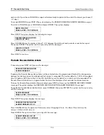
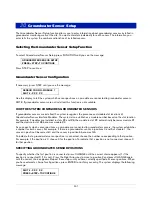
Press STEP. If more than one module is installed, the system automatically advances to the SENSOR CONFIG
message for the next module. Up to 8 modules may be installed. Repeat the steps described above for each
module until you have entered configuration information (sensor positions) for all modules and the system displays
the ENTER SENSOR LOCATION message.
2-Wire C.L. Sensor Location
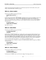
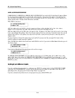
If necessary, press STEP until you see the message:
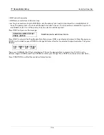
To enter the sensor location, press TANK/SENSOR repeatedly until the sensor you want appears on the second
line of the message (C1, C2, etc.). Press CHANGE and enter the location (up to 20 alphanumeric characters) of
the selected sensor. Typical entries are: INTERSTITIAL-TANK 1; etc. (This information appears on sensor status
and sensor alarm reports to make it easier to identify the location of the alarm.) Press ENTER to confirm your entry:
Press STEP to continue.
2-Wire C.L. Sensor Type
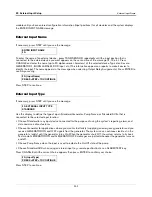
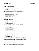
If necessary, press STEP until you see the message:
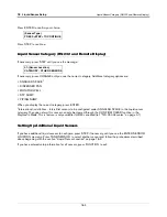
Use this display to identify the selected sensor’s type, so the system can properly interpret and report sensor
information. You can choose DISCRIM INTERSTITIAL or ULTRA 2 for the Sensor Type. DISCRIM INTERSTITIAL
sensors have three sensing states: normal condition, water detection, and fuel detection. ULTRA-2 sensors may
have two sensing states: normal condition and liquid condition.
NOTE: The interstitial sensor for high alcohol applications (Form No. 794380-345) must be set up as
ULTRA 2.
Press STEP to accept DISCRIM INTERSTITIAL. Press CHANGE, then ENTER to accept ULTRA 2, press
CHANGE in response to the ENTER SENSOR TYPE message. Press ENTER to confirm your choice:
Press STEP to continue.
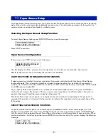
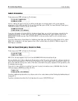
2-Wire C.L. Sensor Category
If necessary, press STEP until you see the message:
ENTER SENSOR LOCATION
C1:
C1: (Sensor Location)
PRESS <STEP> TO CONTINUE
C1: ENTER SENSOR TYPE
DISCRIM INTERSTITIAL
ULTRA 2
PRESS <STEP> TO CONTINUE
C1: (Sensor Location)
CATEGORY: OTHER SENSORS

