


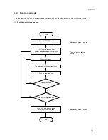


Maintenance
Description
item No.
2DA/2DB
1-4-10
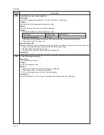
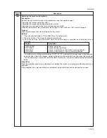
U027
Return of backup data
Description
Transfers the backup data of the EEPROM which was transferred with the U026 to flash memory.
Purpose
To use after the main PCB replaced.
Method
1. Press the start key. The screen for executing is displayed.
2. Select the EXECUTE using the up/down cursor keys. It is displayed in reverse.
3. Press the start key to transfer the backup data.
The screen displays the result.
EXECUTE
CHECK SUM:
∗∗∗∗
CODE : XXXX (See the table below)
Code
Description
0000
Processing ends correctly.
0203
Check sum does not agree when reading out from the EEPROM.
4. Disconnect and connect the power plug.
Completion
Press the stop/clear key. The screen for selecting a maintenance item No. is displayed.
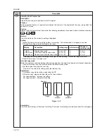
U030
Checking motor operation
Description
Drives each motor.
Purpose
To check the operation of each motor.
Method
1. Press the start key. The screen for selecting an item is displayed.
2. Select the motor to be operated using the up/down cursor keys.
3. Press the start key. The operation starts.
Display
Operation
MAIN
Drive motor (DM) operates
RES
Registration motor (RM) operates
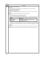
T1
Drawer drive motor 1*
2
(DDM1) operates
T2
Drawer drive motor 2*
1
(DDM2) operates
T3
Drawer drive motor 3*
1
(DDM3) operates
EJE1
Eject motor rotates forward
EJE2
Eject motor rotates in reverse
*1: Optional. *2: Optional for 16 ppm model. Standard for 20 ppm model.
4. To stop operation, press the stop/clear key.
Completion
Press the stop key after operation stops. The screen for selecting a maintenance item No. is displayed.
Summary of Contents for cd 1116
Page 1: ...Service Manual Copy CD 1116 CD 1120 Rev 1 ...
Page 2: ...Service Manual Copy DC 2116 DC 2120 Rev 1 ...
Page 4: ...This page is intentionally left blank ...
Page 247: ...2DA 2DB 1 2 3 2 Figure 2 3 2 Power source PCB silk screen diagram 220 240 V AC 120 V AC ...
Page 264: ...2DA 2DB 1 2 3 19 Figure 2 3 10 Operation unit PCB silk screen diagram ...


