


2DA/2DB
1-4-33
Maintenance
Description
item No.
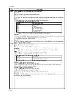
U204
Setting the presence or absence of a key card or key counter
Description
Sets the presence or absence of the optional key card or key counter.
Purpose
To run this maintenance item if a key card or key counter is installed.
Setting
1. Press the start key. The screen for selecting an item is displayed
2. Select the optional counter to be installed using the up/down cursor keys. The selected counter is
displayed in reverse.
Display
Description
OFF
None
KEY-CARD
The key card is installed
KEY-COUNTER
The key counter is installed
3. Press the start key. The setting is set and the screen for selecting a maintenance item No. is displayed.
Completion
Press the stop/clear key. The screen for selecting a maintenance item No. is displayed.
U207
Checking the operation panel keys
Description
Checks operation of the operation panel keys.
Purpose
To check operation of all the keys and LEDs on the operation panel.
Method
1. Press the start key. The screen for executing is displayed.
2. COUNT1 is displayed and the leftmost LED on the operation panel lights.
3. As the keys lined up in the same line as the lit indicator are pressed in the order from the top to the bottom,
the figure shown on the touch panel increases in increments of 1. When all the keys in that line are pressed
and if there are any LEDs corresponding to the keys in the line on the immediate right, the top LED in that
line will light.
4. When all the keys on the operation panel have been pressed, all the LEDs light for up to 10 seconds.
5. When the LEDs go off, press the start key. All the LEDs light for 10 seconds again.
Completion
Press the stop/clear key. The screen for selecting a maintenance item No. is displayed.
Summary of Contents for cd 1116
Page 1: ...Service Manual Copy CD 1116 CD 1120 Rev 1 ...
Page 2: ...Service Manual Copy DC 2116 DC 2120 Rev 1 ...
Page 4: ...This page is intentionally left blank ...
Page 247: ...2DA 2DB 1 2 3 2 Figure 2 3 2 Power source PCB silk screen diagram 220 240 V AC 120 V AC ...
Page 264: ...2DA 2DB 1 2 3 19 Figure 2 3 10 Operation unit PCB silk screen diagram ...


