


2DA/2DB
1-6-29
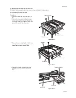
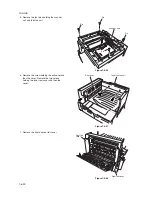
(4) Detaching and refitting the laser scanner unit
Take the following procedure when the laser scanner unit is to be replaced.
Procedure
1. Remove the original cover or the DP.
2. Remove the upper right cover, contact glass,
upper rear cover, middle left cover, upper left
cover, slit glass and front scanner cover (see
page 1-6-23).
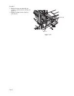
3. Remove the four screws holding the right
cover and then the cover. Remove the seven
screws holding the rear cover and then the
cover.
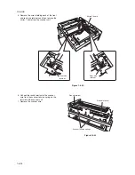
4. Detach the connector YC8 on the main PCB.
Detach the connectors YC16, YC17, YC18
and YC19 on the engine PCB.
Figure 1-6-54
Figure 1-6-55
Rear cover
Right cover
YC8
YC16
YC17
YC18
YC19
Summary of Contents for cd 1116
Page 1: ...Service Manual Copy CD 1116 CD 1120 Rev 1 ...
Page 2: ...Service Manual Copy DC 2116 DC 2120 Rev 1 ...
Page 4: ...This page is intentionally left blank ...
Page 247: ...2DA 2DB 1 2 3 2 Figure 2 3 2 Power source PCB silk screen diagram 220 240 V AC 120 V AC ...
Page 264: ...2DA 2DB 1 2 3 19 Figure 2 3 10 Operation unit PCB silk screen diagram ...


