


1-3-34
2DA/2DB
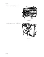
14. Connect the pulled out connector of the job separator
to the LED PCB of the left front cover JS and then
pass the wire through the two positions of the groove
of the left front cover JS.
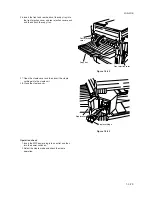
15. Fit the pawl of the left front cover JS into the hole of
the left front cover to attach the left front cover JS.
* In this time, take care that the routed wire in the
groove does not come off.
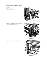
16. Attach the inner cover that has been removed by
Procedure 2 to its original position.
17. Close the front cover.
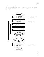
Operation check
1. Insert the power plug of the MFP into an outlet and
then turn the power switch on.
2. Set the “copy ejection location” of the machine
default settings to job separator.
3. Make a test copy to check that a copy is ejected to
the job separator tray.
Grooves
Left front cover JS
LED PCB
Connector
Holes
Left front cover JS
Figure 1-3-63
Figure 1-3-64
Summary of Contents for cd 1116
Page 1: ...Service Manual Copy CD 1116 CD 1120 Rev 1 ...
Page 2: ...Service Manual Copy DC 2116 DC 2120 Rev 1 ...
Page 4: ...This page is intentionally left blank ...
Page 247: ...2DA 2DB 1 2 3 2 Figure 2 3 2 Power source PCB silk screen diagram 220 240 V AC 120 V AC ...
Page 264: ...2DA 2DB 1 2 3 19 Figure 2 3 10 Operation unit PCB silk screen diagram ...


