


2DA/2DB
1-5-22
Code
Contents
Remarks
Causes
Check procedures/corrective measures
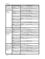
C3300
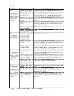
C4000
C4010
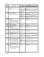
C4200
C6000
Optical system (AGC) problem
• After AGC, correct input is not ob-
tained at CCD.
Polygon motor synchronization
problem
• The polygon motor does not reach
the stable speed within 15 s of the
START signal turning on.
Polygon motor steady-state problem
• The polygon motor rotation is not
stable for 5 s after the polygon motor
rotation has been stabilized.
BD steady-state problem
• The MIP detects a BD error for 600
ms after the polygon motor rotation
has been stabilized.
Broken fixing heater wire
• In fixing warm-up, the time to reach
50°C/122 °F exceeds 13.5 s, the time
to reach 100°C/212 °F exceeds 10 s,
the time to reach the primary stabili-
zation exceeds 10 s or the time to
reach the secondary stabilization ex-
ceeds 24 s.
Insufficient expo-
sure lamp lumi-
nosity.
Defective engine
PCB.
Incorrect shading
position.
Defective CCD
PCB.
Poor contact in
the polygon motor
connector termi-
nals.
Defective polygon
motor.
Defective engine
PCB.
Poor contact in
the polygon motor
connector termi-
nals.
Defective polygon
motor.
Defective engine
PCB.
Defective laser
diode.
Defective polygon
motor.
Defective main
PCB.
Defective engine
PCB.
Poor contact in
the thermistor
connector termi-
nals.
Fixing thermistor
installed incor-
rectly.
Fixing thermostat
triggered.
Replace the exposure lamp or inverter
PCB.
Replace the engine PCB and check for
correct operation.
Adjust the position of the contact glass
(shading plate). If the problem still occurs,
replace the scanner home position switch.
Replace the ISU.
Reinsert the connector. Also check for con-
tinuity within the connector cable. If none,
remedy or replace the cable.
Replace the LSU.
Replace the engine PCB and check for
correct operation.
Reinsert the connector. Also check for con-
tinuity within the connector cable. If none,
remedy or replace the cable.
Replace the LSU.
Replace the engine PCB and check for
correct operation.
Replace the LSU.
Replace the LSU.
Replace the main PCB and check for cor-
rect operation.
Replace the engine PCB and check for
correct operation.
Reinsert the connector. Also check for con-
tinuity within the connector cable. If none,
remedy or replace the cable.
Check and reinstall if necessary.
Check for continuity. If none, replace the
fixing thermostat.
Summary of Contents for cd 1116
Page 1: ...Service Manual Copy CD 1116 CD 1120 Rev 1 ...
Page 2: ...Service Manual Copy DC 2116 DC 2120 Rev 1 ...
Page 4: ...This page is intentionally left blank ...
Page 247: ...2DA 2DB 1 2 3 2 Figure 2 3 2 Power source PCB silk screen diagram 220 240 V AC 120 V AC ...
Page 264: ...2DA 2DB 1 2 3 19 Figure 2 3 10 Operation unit PCB silk screen diagram ...


