


2DA/2DB
1-5-21
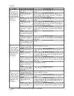
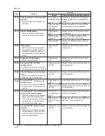
Code
Contents
Remarks
Causes
Check procedures/corrective measures
C0890
C0900
C0920
C2000
C3100
C3200
Fax control PCB
*
1
CG font archive
problem
• When power is turned on, the com-
pressed CG font in the Flash ROM on
the fax control PCB was not success-
fully decompressed.
Fax software incompatibility detec-
tion problem
• Version of fax software is not compat-
ible with that of main software.
Fax file system error
• The backup data is not retained for
file system abnormality of flash
memory of the fax control PCB.
Drive motor problem
• LOCK ALM signal remains high for 1
s, 1 s after the drive motor has turned
on.
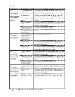
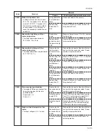
Scanner carriage problem
• The home position is not correct
when the power is turned on or copy-
ing the document placed on the con-
tact glass.
Exposure lamp problem
• Non-lighting of the exposure lamp is
detected at the beginning of copying.
Defective fax con-
trol PCB.
Fax software ver-
sion or main soft-
ware is earlier.
Defective fax con-
trol PCB.
Poor contact in
the drive motor
connector termi-
nals.
Defective drive
motor rotation
control circuit.
Defective drive
transmission sys-
tem.
Poor contact of
the connector ter-
minals.
Defective scanner
home position
switch.
Defective engine
PCB.
Defective scanner
motor.
Poor contact of
the connector ter-
minals.
Defective expo-
sure lamp or in-
verter PCB.
Defective engine
PCB.
Incorrect shading
position.
Replace the fax control PCB and check for
correct operation.
Check the version of the fax software and
the main software, upgrade the version to
the compatible software.
Replace the fax control PCB and check for
correct operation.
Reinsert the connector. Also check for con-
tinuity within the connector cable. If none,
remedy or replace the cable.
Replace the drive motor.
Check if the rollers and gears rotate
smoothly. If not, grease the bushings and
gears. Check for broken gears and replace
if any.
Reinsert the connector. Also check for con-
tinuity within the connector cable. If none,
remedy or replace the cable.
Replace the scanner home position switch.
Replace the engine PCB and check for
correct operation.
Replace the scanner motor.
Reinsert the connector. Also check for con-
tinuity within the connector cable. If none,
remedy or replace the cable.
Replace the exposure lamp or inverter
PCB.
Replace the engine PCB and check for
correct operation.
Adjust the position of the contact glass
(shading plate). If the problem still occurs,
replace the scanner home position switch.
*1: Optional. *2: Optional for 16 ppm model. Standard for 20 ppm model.
Summary of Contents for cd 1116
Page 1: ...Service Manual Copy CD 1116 CD 1120 Rev 1 ...
Page 2: ...Service Manual Copy DC 2116 DC 2120 Rev 1 ...
Page 4: ...This page is intentionally left blank ...
Page 247: ...2DA 2DB 1 2 3 2 Figure 2 3 2 Power source PCB silk screen diagram 220 240 V AC 120 V AC ...
Page 264: ...2DA 2DB 1 2 3 19 Figure 2 3 10 Operation unit PCB silk screen diagram ...


