


1-3-36
2DA/2DB
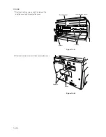
Remove the shield cover.
7. Remove the six screws, lift the shield cover and then
remove the cover.
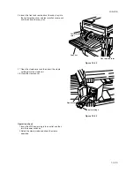
Remove the modular cover.
8. Remove the screw and take off the modular cover.
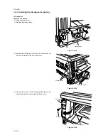
Attach the fax control PCB assembly.
9. Loosen the screw on the printer board.
10. While taking care that the mounting surface of the
board does not contact the frame section of the rear
cover, insert the U terminal of the ground wire of the
fax control PCB assembly and secure it with the
screw.
Screws
Screws
Shield cover
Screw
Modular cover
Fax control PCB assembly
Screw
Ground wire
Frame section
Figure 1-3-67
Figure 1-3-69
Figure 1-3-68
Summary of Contents for cd 1116
Page 1: ...Service Manual Copy CD 1116 CD 1120 Rev 1 ...
Page 2: ...Service Manual Copy DC 2116 DC 2120 Rev 1 ...
Page 4: ...This page is intentionally left blank ...
Page 247: ...2DA 2DB 1 2 3 2 Figure 2 3 2 Power source PCB silk screen diagram 220 240 V AC 120 V AC ...
Page 264: ...2DA 2DB 1 2 3 19 Figure 2 3 10 Operation unit PCB silk screen diagram ...


