


134
6. Tighten setscrews and replace panel(s).
7. Turn on unit power.
Four-Inch Filter Replacement —
The 4-Inch Filter
Change Mode variable is used to service the unit when 4-in.
filters are used. When the filters need to be changed, set
Service Test
F.4.CH
= YES
. The unit will be placed in
Service Test mode and the economizer will move to the 40%
open position to facilitate removal of the 4-in. filters. After the
filters have been changed, set
Service Test
F.4.CH
= NO
to
return the unit to normal operation.
Power Failure —
The economizer damper motor is a
spring return design. In event of power failure, dampers will
return to fully closed position until power is restored.
Refrigerant Charge —
Amount of refrigerant charge is
listed on unit nameplate. Refer to Carrier GTAC II; Module 5;
Charging, Recovery, Recycling, and Reclamation section for
charging methods and procedures.
Unit panels must be in place when unit is operating during
charging procedure.
NOTE: Do not use recycled refrigerant as it may contain
contaminants.
NO CHARGE — Use standard evacuating techniques. After
evacuating system, weigh in the specified amount of refriger-
ant from the unit nameplate.
LOW CHARGE COOLING
All Units with Round Tube-Plate Fin Condenser Coils —
Connect the gage set and a temperature-measuring device to
the liquid line. Ensure that all condenser fans are operating. It
may be necessary to block part of the coil on cold days to
ensure that condensing pressures are high enough to turn on
the fans. Adjust the refrigerant charge in each circuit to obtain
state point liquid subcooling for specific models as listed in
Table 111.
NOTE: Indoor-air cfm must be within normal operating range
of unit.
Table 111 — Round Tube, Plate Fin Unit Charge
48/50A2,A3,A4,A5 Units with MCHX Condenser — Due
to the compact, all aluminum design, microchannel heat
exchangers will reduce refrigerant charge and overall operating
weight. As a result, charging procedures for MCHX units
require more accurate measurement techniques. Charge should
be added in small increments. Using cooling charging charts
provided (Fig. 48-54), add or remove refrigerant until
conditions of the chart are met. As conditions get close to the
point on the chart, add or remove charge in
1
/
4
lb increments
until complete. Ensure that all fans are on and all compressors
are running when using charging charts.
To Use the Cooling Charging Chart — Use the outdoor air
temperature, saturated suction temperature and saturated con-
densing temperature (available on the
Comfort
Link display),
and find the intersection point on the cooling charging chart. If
intersection point is above the line, carefully recover some of
the refrigerant. If intersection point is below the line, carefully
add refrigerant.
NOTE: Indoor-air cfm must be within normal operating range
of unit.
Units with Humidi-MiZer Adaptive Dehumidification Sys-
tem — All circuits must be running in normal cooling mode.
Indoor airflow must be within specified air quantity limits for
cooling. All outdoor fans must be on and running at normal
speed.
Use the following procedure to adjust charge on Circuit B of
Humidi-MiZer equipped units:
1. Start all compressors and outdoor fans. Allow unit to run
for 5 minutes.
2. Switch system to run in a Dehumidification mode for 5
minutes by switching
RHV
to ON through the Service
Test function (
Service Test
COOL
RHV
).
3. At the end of the 5-minute period, switch back into Cool-
ing mode through the Service Test function (
Service
Test
COOL
RHV
) by switching RHV to OFF.
4. Using the cooling charging charts provided (Fig. 48-54),
add or remove refrigerant until conditions of the chart are
met. As conditions get close to the point on the chart, add
or remove charge in
1
/
4
lb increments until complete. See
paragraph "To Use the Cooling Charging Chart" for addi-
tional instructions.
5. If a charge adjustment was necessary in Step 4, then re-
peat the steps in this paragraph (starting with Step 2) until
no charge adjustment is necessary. When no more charge
adjustment is necessary after switching from a Dehumidi-
fication Mode to a Cooling Mode (Steps 2 and 3), then
the charge adjustment procedure is complete.
Thermostatic Expansion Valve (TXV)
Each circuit has
a TXV. The TXV is adjustable and is factory set to maintain 8 to
12° F superheat leaving the evaporator coil. The TXV controls
flow of liquid refrigerant to the evaporator coils. Adjusting the
TXV is not recommended.
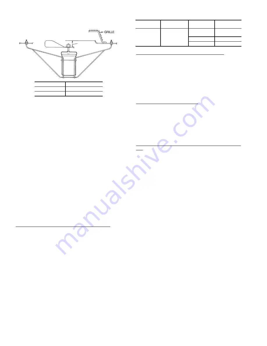
A
Fig. 47 — Condenser-Fan Adjustment
(All Units Except Size 060 MCHX)
UNIT SIZE
DIMENSION “A” (in.)
020-035, 050
1.30 ± 0.12
040, 060
0.87 ± 0.12
UNIT
48/50
REFRIGERANT
TYPE
SIZE
LIQUID
SUBCOOLING
A2,A3,A4,A5
R-410A
020, 027, 040,
050, 060
15 F ± 2 F
030, 035
20 F ± 2 F
025
12 F ± 2 F
Summary of Contents for Carrier Weathermaker 48A2
Page 105: ...105 Fig 20 Typical Main Control Box Wiring Schematic 48 50A2 A3 A4 A5 Units...
Page 106: ...106 Fig 21 Typical Auxiliary Control Box Wiring Schematic...
Page 107: ...107 Fig 22 Typical 2 Stage Gas Heat Wiring Schematic Size 060 Units Shown a48 8357...
Page 108: ...108 TO NEXT PAGE Fig 23 Typical Staged Gas Heat Wiring Schematic Size 060 Units Shown A48 7296...
Page 109: ...109 Fig 23 Typical Staged Gas Heat Wiring Schematic Size 060 Units Shown cont A48 8358...
Page 110: ...110 Fig 24 Typical Electric Heat Control Schematic 50 Series Size 060 Units Shown a50 8228...
Page 111: ...111 Fig 25 Typical Power Schematic 48 50A2 A3 A4 A5 060 Unit Shown...
Page 112: ...112 Fig 26 Typical Low Ambient Controls Option Wiring...
Page 113: ...113 Fig 27 Typical Small Chassis Component Location Size 020 035 Units...
Page 114: ...114 Fig 28 Typical Large Chassis Component Locations Size 040 060 Units...
Page 118: ...118 Fig 30 Economizer Control Board ECB1 and VAV Control Board ECB2 A48 7706...
Page 142: ...142 A48 3733 Fig 56 Main Burner Removal...
Page 176: ...176 APPENDIX C VFD INFORMATION cont Fig F Internal Enclosure Fan Replacement A48 7716...


