


133
9. Torque nuts properly to 95 to 100 ft-lb. Do not turn a cou-
pling bolt. Always turn the nut. Always use thread lubri-
cant or anti-seize compound to prevent thread galling.
10. The ends of the shafts should be flush with the inside of
the shaft flange. Torque the set screws to 25 ft-lb.
11. After assembly is complete, slowly rotate the shafts by
hand for 30 to 60 seconds.
12. Tighten the bearing mounting bolts, using care not to
place any loads on the shaft which would cause flexure to
the shafts.
13. Reinstall drive belts. (Refer to Belt Tension Adjustment
section below.)
14. Visually inspect the assembly. If the shafts are overly mis-
aligned, the drive shaft flange will not be parallel with the
shaft flanges.
15. Recheck nut torque after 1 to 2 hours of operation. Bolts
tend to relax after being initially torqued.
Evaporator Fan Service and Replacement
1. Turn off unit power supply.
2. Remove supply-air section panels.
3. Remove belt and blower pulley.
4. Loosen setscrews in blower wheels.
5. Remove locking collars from bearings.
6. Remove shaft.
7. Remove venturi on opposite side of bearing.
8. Lift out wheel.
9. Reverse above procedure to reinstall fan.
10. Check and adjust belt tension as necessary.
11. Restore power to unit.
Belt Tension Adjustment —
To adjust belt tension:
1. Turn off unit power supply.
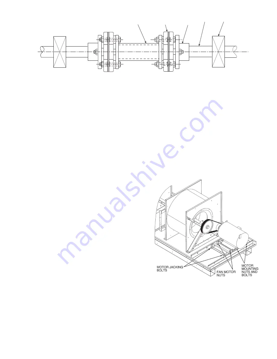
2. Loosen motor mounting nuts and bolts. See Fig. 46.
3. Loosen fan motor nuts.
4. Turn motor jacking bolts to move motor mounting plate
left or right for proper belt tension. A slight bow should
be present in the belt on the slack side of the drive while
running under full load.
5. Tighten nuts.
6. Adjust bolts and nut on mounting plate to secure motor in
fixed position. Recheck belt tension after 24 hours of
operation. Adjust as necessary. Refer to Installation In-
structions for proper tension values.
7. Restore power to unit.
Evaporator-Fan Motor Replacement
1. Turn off unit power supply.
2. Remove upper outside panel and open hinged door to
gain access to motor.
3. Fully retract motor plate adjusting bolts.
4. Loosen the 2 rear (nearest the evaporator coil) motor plate
nuts.
5. Remove the 2 front motor plate nuts and carriage bolts.
6. Slide motor plate to the rear (toward the coil) and remove
fan belt(s).
7. Slide motor plate to the front and hand tighten one of the
rear motor plate nuts (tight enough to prevent the motor
plate from sliding back but loose enough to allow the
plate to pivot upward).
8. Pivot the front of the motor plate upward enough to allow
access to the motor mounting hex bolts and secure in
place by inserting a prop.
9. Remove the nuts from the motor mounting hex bolts and
remove motor.
10. Replace the locktooth washer under the motor base with a
new washer. Be sure that the washer contacts the motor
base surface.
11. Reverse above steps to install new motor.
Condenser-Fan Adjustment
NOTE: Condenser fans on size 060 MCHX units are not
adjustable.
1. Turn off unit power supply.
2. Remove fan guard.
3. Loosen fan hub setscrews.
4. Adjust fan height on shaft using a straightedge placed
across venturi and measure per Fig. 47.
5. Fill hub recess with permagum if rubber hubcap is missing.
CENTER DRIVE
SHAFT
FLEX
MEMBER
SHAFT
FLANGE
BEARINGS
SHAFT
Fig. 45 — Evaporator Fan Coupling
A50-5146
Fig. 46 — Belt Tension Adjustment
A48-3729
Summary of Contents for Carrier Weathermaker 48A2
Page 105: ...105 Fig 20 Typical Main Control Box Wiring Schematic 48 50A2 A3 A4 A5 Units...
Page 106: ...106 Fig 21 Typical Auxiliary Control Box Wiring Schematic...
Page 107: ...107 Fig 22 Typical 2 Stage Gas Heat Wiring Schematic Size 060 Units Shown a48 8357...
Page 108: ...108 TO NEXT PAGE Fig 23 Typical Staged Gas Heat Wiring Schematic Size 060 Units Shown A48 7296...
Page 109: ...109 Fig 23 Typical Staged Gas Heat Wiring Schematic Size 060 Units Shown cont A48 8358...
Page 110: ...110 Fig 24 Typical Electric Heat Control Schematic 50 Series Size 060 Units Shown a50 8228...
Page 111: ...111 Fig 25 Typical Power Schematic 48 50A2 A3 A4 A5 060 Unit Shown...
Page 112: ...112 Fig 26 Typical Low Ambient Controls Option Wiring...
Page 113: ...113 Fig 27 Typical Small Chassis Component Location Size 020 035 Units...
Page 114: ...114 Fig 28 Typical Large Chassis Component Locations Size 040 060 Units...
Page 118: ...118 Fig 30 Economizer Control Board ECB1 and VAV Control Board ECB2 A48 7706...
Page 142: ...142 A48 3733 Fig 56 Main Burner Removal...
Page 176: ...176 APPENDIX C VFD INFORMATION cont Fig F Internal Enclosure Fan Replacement A48 7716...


