


-13-
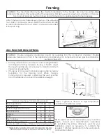
FLOOR SUPPORT AND PROTECTION
•
If installed directly on carpeting, tile, or other combustible material other than wood flooring, this appliance
shall be installed on a metal or wood panel extending the full width and depth of the appliance.
•
If installed above floor level, a solid, continuous platform must be constructed below the appliance.
•
Consider the height of hearth finish material (stone, brick, etc.) when building a platform. The bottom of the
appliance must be level with finished hearth to allow for a proper fit of the safety barriers.
• Build the hearth to desired size and height. If a hearth extension is desired, combustible material may be used.
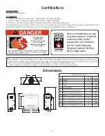
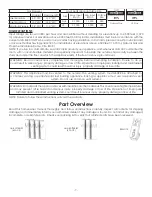
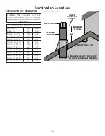
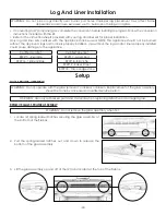
VENT TERMINATION FRAMING
NOTE: Vent cap location must be in compliance with the
minimum termination clearance information listed in this manual.
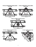
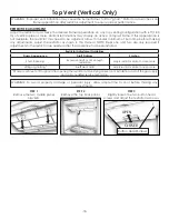
15-1/2”
(394mm)
39”
(991mm)
Top Vent Minimum
Horizontal Venting
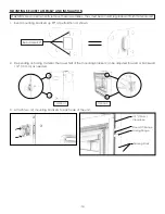
WARNING: FIRE HAZARD: Do NOT install directly on carpeting, vinyl, or any other combustible material other
than wood.
WARNING: DO NOT RECESS THE VENT CAP INTO WALL OR SIDING.
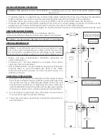
VERTICAL TERMINATIONS
• Follow vent pipe manufacturer’s installation instructions for
vertical terminations.
• A minimum of 1” (25 mm) clearance on all sides of the vertical
vent pipe must be maintained.
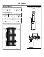
• Attic insulation shields may be insulated using unfaced insulation
products listed as non-combustible per ASTM E 136. NOTE:
Horizontal vent sections require 1/4 in (6 mm) rise for every 12 in
(305 mm) of travel.
HORIZONTAL TERMINATIONS
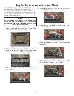
1.
Measure from floor level of the appliance to the center of where
the vent pipe will penetrate the wall. Elbows listed with approved
vent systems will vary in vertical length. Please consult the vent
manufacturer’s instructions to determine the elbow dimension
used for installation. Adjust the wall pass-through rough opening
dimensions as necessary to maintain clearance requirements.
2. Cut and frame an opening in the wall to allow the vent system
to run level through the wall pass-through.
3. Follow the vent pipe manufacturer’s installation instructions for
vent installation.
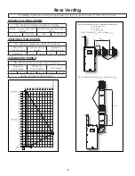
WARNING: Cold air transfer area. The surround appliance chase
must comply with all clearances as outlined in this manual, and
be constructed in compliance with local building codes. Outside
walls should be insulated to prevent cold air from entering room.
15-1/2”
(394mm)
26”
(660.5mm)
Rear Vent Minimum
Horizontal Venting
End View
End View


