


-41-
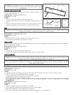
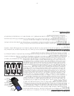
GAS FLAME ADJUSTMENT
WARNING: VENTURI ADJUSTMENT MUST BE DONE BY A QUALIFIED SERVICE TECHNICIAN.
During the initial installation, the air shutter opening should be checked to be certain that the shutter is set
correctly as specified in this manual. Adjustments should only be made by a qualified installer. NOTE: For altitudes
above 5,000 ft., some variations may be required.
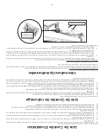
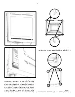
Be sure burner and logs are properly installed. After burner has been properly installed and operated for 2-3 hours,
small additional adjustments to the air shutter may be necessary for final flame appearance. These small shutter
adjustments can be made by the following procedure. NOTE: Very small changes in shutter settings make major
changes in flame appearance.
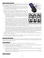
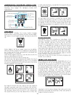
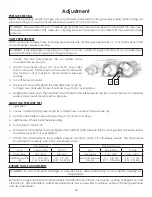
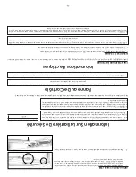
1. Air shutter controls are located at the bottom of the appliance next to the valve assembly.
2.
If flame is too “blue,” push the air shutter knob in (close) in small 1/8” increments until flame turns desired
realistic “orange” color.
3.
If flame is too “orange” or is causing sooting on viewing glass, pull air shutter knob out (open) in approx. 1/8”
increments until sooting stops.
WARNING: Try each new shutter setting approx. 1/2 hr. before making additional changes. Changes in burner
flame can be made by re-arranging the media material.
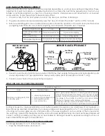
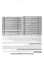
Factory Set Venturi Openings
Fuel
Air Shutter Opening
Natural Gas
Closed
LP Gas
1/8” (3 mm) Open
Air Shutter Controls
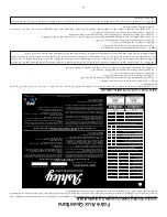
Troubleshooting
Before proceeding with the steps in the following troubleshooting guide,
• Verify proper 120VAC power supply to the control module.
• Verify the control module battery pack and the remote control batteries are fresh and installed with correct
polarity.
• Verify all connections between the wire harnesses and the system components are proper and positive.
• Verify the communication link is established between the remote control and the ignition module.
• Verify inlet pressure meets the recommended inlet pressure.
If necessary, adjust line pressure regulator.
Issue
Cause
Solution
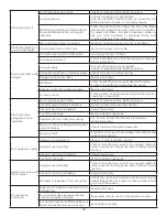
Pilot will not light
Electrical power interrupted or
disconnected
Restore electrical power to appliance or use battery
back-up.
Wiring disconnection
Ensure batteries are fully charged if using battery back-
up as power source.
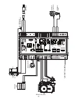
Use wiring schematic in this manual to determine that
all wiring connections are secure and correct.
Gas supply turned off
Check remote shut-off valves from the appliance.
Usually there is a valve near the main gas line. There
may be more than (1) valve between the appliance
and main gas line.
WARNING: Installation and repair shall only be done by a qualified service person. The appliance should be
inspected before use by a qualified service person. It is required to be inspected at least once a year by a
professional service person.


