-15-
10”
(254 mm)
14”
(356 mm)
9”
(229 mm)
½” (13mm)
NON-COMBUSTIBLE
MATERIAL ONLY
SINGLE VERTICAL
HEADER
MANTEL
47”
(1194 mm)
FINISHING RECOMMENDATIONS
The surface area above the appliance may be affected
by emitted high temperatures. To help avoid or reduce
the possibility of the sheetrock to crack the following
methods are recommended:
• Ensure the non-combustible material and sheetrock
is dry and dust free.
• For taping and mudding seams, we recommend heat
resilient tape, mesh and joint compounds. Mud must
be cured as per manufacturer’s recommendations.
• For a painted surface, use a high quality acrylic latex
primer and finish coat. Avoid flat or light-colored
paints to prevent discoloring.
Gas Line Connection
WARNING: The conversion shall be carried out in accordance with the requirements of the provincial authorities
having jurisdiction and in accordance with the requirements of the ANSI Z223.1 installation code.
GAS CONVERSION (SOLD SEPARATELY)
This appliance is manufactured for use with natural gas. Follow the instructions included with the AG30LPC
conversion kit if converting to LP gas. The conversion kit shall be installed by a qualified service agency.
GAS LINE INSTALLATION
NOTE: The appliance and its individual shutoff valve must be disconnected from the gas supply piping system
during any pressure testing of that system at pressures in excess of 1/2 psi (3.5 kPa). For test pressures equal to
or less than 1/2 psi (3.5 kPa), the appliance must be isolated from the gas supply piping system by closing its
individual manual shut-off valve.
A listed (and Commonwealth of Massachusetts approved) 1/2” (13 mm) tee handle manual shut-off valve and
flexible gas connector are to be connected to the 1/2” (13 mm) control valve inlet. If substituting for these
components, please consult local codes for compliance.
•
This appliance is equipped with a 3/8” (10 mm) x 18” (457 mm) long flexible gas connector and manual shut-
off valve.
• Run gas line into appliance. The gas line should be run to the point of connection where the shut-off valve and
flexible gas line will connect.
• Do not run gas line in a manner that would obstruct fan operation.
• For high altitude installations, consult the local gas distributor or the authority having jurisdiction for proper
rating methods.
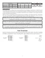
Inlet Gas Supply Pressures
Fuel
Minimum Pressure
Maximum Pressure
Natural Gas
5” WC (1.25 kPa)
10.5” WC (2.62 kPa)
LP Gas
12” WC (2.674 kPa)
14” WC (3.49 kPa)
WARNING: Installation of the gas line must only be done by a qualified person in accordance with local
building codes, if any. If not, follow ANSI 223.1. Commonwealth of Massachusetts installations must be done by
a licensed plumber or gas fitter.
Mantel And Finishing Requirements

