26
VI. ELECTRICAL (continued)
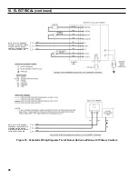
NOTE: APPLy THIS BURNER
SCHEMATIC TO APPROPRIATE
STEAM OR WATER BOILER
CONTROL SCHEMATIC, REFER
TO FIGURES 15A AND 15B
NOTE: APPLy THIS BURNER
SCHEMATIC TO APPROPRIATE
STEAM OR WATER BOILER
CONTROL SCHEMATIC, REFER
TO FIGURES 15A AND 15B
Figure 16: Schematic Wiring Diagrams For All Burner Options w/Various Oil Primary Controls
Summary of Contents for LE DV Series
Page 5: ...5 I General Information Figure 1A LEDV Packaged Water Boiler with Beckett AFII Burner ...
Page 6: ...6 I General Information continued Figure 1B LEDV Packaged Water Boiler with Riello BF Burner ...
Page 19: ...19 v venting continued Figure 11 Vent Installation Figure 12 Vent Connector Un Assembled ...
Page 20: ...20 v venting continued Figure 13 Vent Connector Assembled Figure 14 Air Intake Installation ...
Page 48: ...48 xiii Repair Parts continued Figure 29 LEDV Bare Boiler Assembly ...
Page 50: ...50 xiii Repair Parts continued Figure 30 LEDV Boiler Jacket Insulation ...
Page 55: ...55 xiii Repair Parts continued Figure 33 Vent Kit Repair Parts ...
Page 60: ...60 U S Boiler Company Inc P O Box 3020 Lancaster PA 17604 1 888 432 8887 www usboiler net ...


