38
IX. OPERATING (continued)
Call for Heat
Circulator Status
T-T
Input
ZR
Input
C1
Output
ZC
Output
off
off
off
off
on
off
on
off
on
on
on
on
off
on
off
on
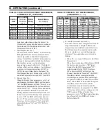
TABLE 11: ZONE REqUEST, PARAmETER
ZC_
=
ZR
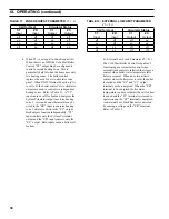
TABLE 12: EXTERNAL LOW LImIT, PARAmETER
ZC_
=
ELL
Call for Heat
Circulator Status
T-T
Input
ZR
Input
C1
Output
ZC
Output
off
off
off
on
on
off
on
on
on
on
off
off
off
on
off
off
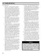
ii.
When
ZC_
is set equal to Zone Request (
ZR
)
When there is no IWH the Cold Start Boiler
Control “ZC” output may be configured to
control a second heating zone. This is
particularly helpful when the home uses only
two heating zones. The boiler control
replaces the need for a two circulator zone
panel. When DHW Terminal Function (
dh_
)
is set to
ZR
the boiler control’s two circulator
outputs are used to control two independent
heating zones. Refer to Table 11. A “TT”
input causes a call for heat and energizes the
System Circulator output to service heating
zone 1. A second zone’s thermostat may be
wired to the “ZR” input to energize heating
zone 2 circulator wired to the “ZC” output.
Both outputs function independently, “TT”
input controls only the System Circulator
output and the “ZR” input controls only the
“ZC” output. Both inputs cause a boiler call
for heat.
iii.
External Low Limit, Parameter
ZC
=
ELL
The Cold Start Boiler Control is capable of
functioning as a warm start control when
external limit control is installed that closes a
contact when boiler water temperature falls
below a setpoint. When an external limit
contact closes (boiler water is cold) the boiler
is started and the “ZC” and “C1” output
terminals are de-energized. When the “ZR”
terminal is de-energized (boiler water
temperature is above setpoint) the call for heat
is ended and the “C1” terminal is released to
operation and the “ZC” terminal is energized.
An External Low Limit Request is detected
by sensing a voltage on the “ZR” terminal.
Refer to Table 12.
Summary of Contents for LE DV Series
Page 5: ...5 I General Information Figure 1A LEDV Packaged Water Boiler with Beckett AFII Burner ...
Page 6: ...6 I General Information continued Figure 1B LEDV Packaged Water Boiler with Riello BF Burner ...
Page 19: ...19 v venting continued Figure 11 Vent Installation Figure 12 Vent Connector Un Assembled ...
Page 20: ...20 v venting continued Figure 13 Vent Connector Assembled Figure 14 Air Intake Installation ...
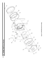
Page 48: ...48 xiii Repair Parts continued Figure 29 LEDV Bare Boiler Assembly ...
Page 50: ...50 xiii Repair Parts continued Figure 30 LEDV Boiler Jacket Insulation ...
Page 55: ...55 xiii Repair Parts continued Figure 33 Vent Kit Repair Parts ...
Page 60: ...60 U S Boiler Company Inc P O Box 3020 Lancaster PA 17604 1 888 432 8887 www usboiler net ...


