30
VIII. SySTEm START-UP (continued)
2. PRESS RED RESET BUTTON on burner primary
control, hold for one second and release to reset the
control.
3. WATER BOILERS WITHOUT TANKLESS
HEATERS are equipped with an Intelligent Oil
Boiler Control (Cold Start Boiler Control). The
Boiler Control is factory programmed with a High
Limit setpoint of 180°F. The High Limit setpoint is
adjustable between 140°F and 240°F. This tempera-
ture may be varied to suit the installation require-
ments.
HIGH LIMIT DIFFERENTIAL is factory pro-
grammed at 15°F and is adjustable between 10°F
and 30°F.
4. CHECKOUT
Put the system into operation and observe at least
one complete cycle to make sure that the controller
operates properly. See Troubleshooting Section to
use LED to assist in determining system operation.
E.
BURNER START-UP
WARNING
Do not attempt to start the burner when excess
oil has accumulated in the chamber, when boiler
is full of vapor or when combustion chamber is
very hot.
1. VERIFy burner settings.
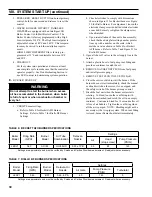
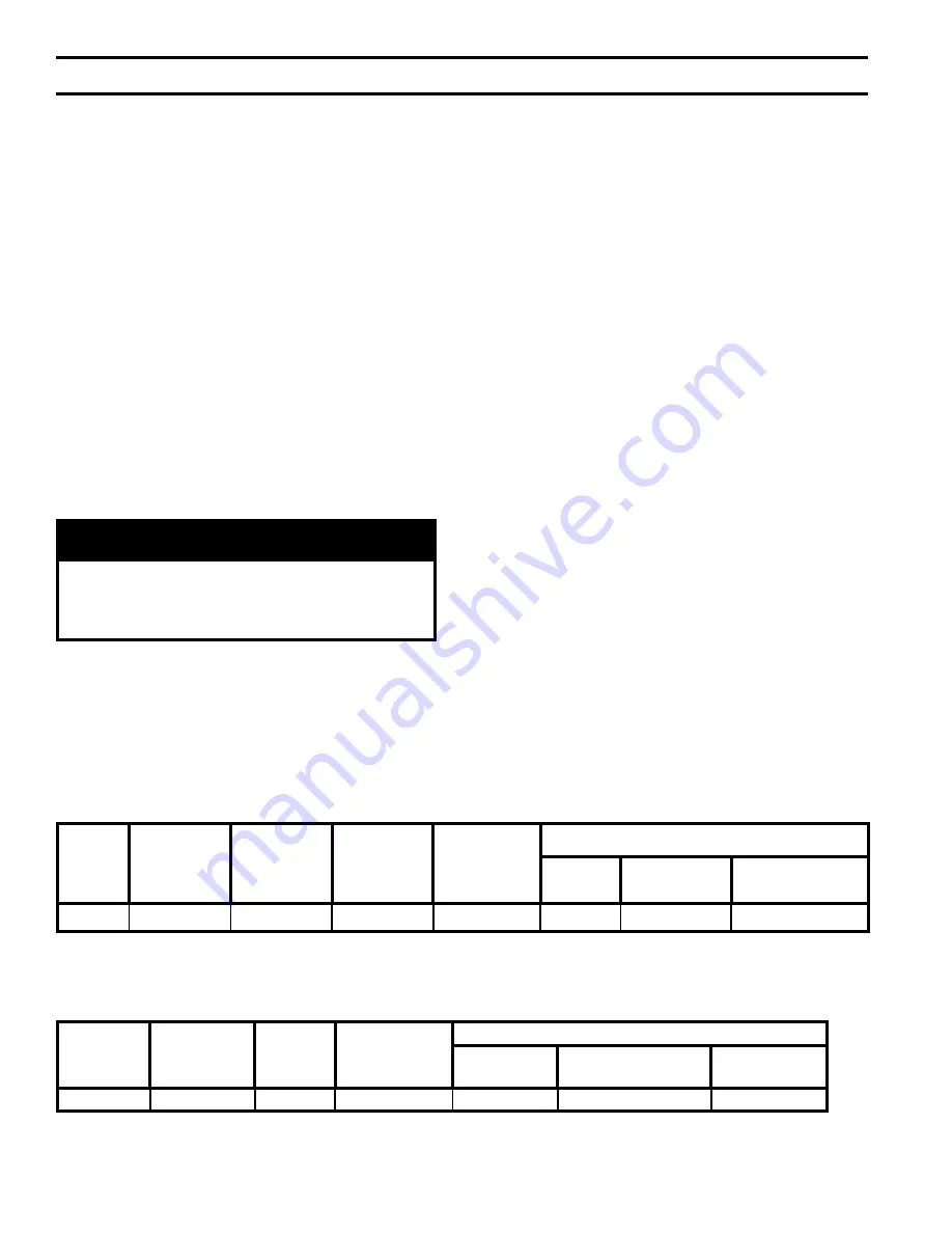
a. Refer to Table 6 for Beckett AFII Burner
Settings. Refer to Table 7 for Riello BF Burner
Settings.
TABLE 6: BECKETT AFII BURNER SPECIFICATIONS
TABLE 7: RIELLO BF BURNER SPECIFICATIONS
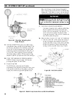
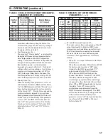
b. Check electrodes to comply with dimensions
shown in Figure 19 for Beckett burner or Figure
20 for Riello Burner. For adjustment, loosen the
electrode clamp screw and slide/rotate electrodes
as needed. Securely re-tighten the clamp screw
when finished.
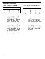
c. Upon reinstallation of the nozzle line assembly,
check that head/air plate setting number pointer
lines up with a number on the scale, which
matches a value shown in Table 6 for Beckett
AFII burner. Refer to Table 7 and Figure 21 for
Riello BF burner.
2. Open all shut-off valves in the oil supply line to the
burner.
3. Attach a plastic hose to fuel pump vent fitting and
provide a container to catch the oil.
4. REMOVE GAUGE PORT PLUG from fuel pump
and install pressure gauge.
5. REMOVE TEST PLUG IN FLUE COLLAR.
6. Close the service switch to start the burner. If the
burner does not start immediately, check the manual
overload switch on the motor, if so equipped, and
the safety switch of the burner primary control.
7. Bleed the fuel unit when the burner motor starts
rotating. To bleed, loosen the vent fitting (with
plastic hose attached) and catch the oil in an empty
container. Continue to bleed for 15 seconds after oil
is free of air bubbles. Tighten the vent fitting when
all the air is purged. NOTE: Bleeding might not be
necessary with a two pipe system. When vent fitting
is closed, burner flame should start immediately.
Boiler
Model
Firing Rate
(GPH)
Burner
Model
Air Tube
Combination
Delavan
Nozzle
Settings
Air
Head
(stop screw)
Pump Pressure
(PSIG)
LEDV1
0.60
AFII 85
HLX50HD
0.50 x 70°B
2.5
#2
140
Settings are approximate and must be verified by Smoke and Carbon Dioxide measurement. Readjust where necessary.
Boiler
Model
Firing Rate
(GPH)
Burner
Model
Delavan Oil
Nozzle
Settings
Air Gate
Pump Pressure
(PSIG)
Turbulator
LEDV1
0.60
BF3
0.50 - 60° A
4.0
145
0
Settings are approximate and must be verified by Smoke and Carbon Dioxide measurement. Readjust where necessary.
Summary of Contents for LE DV Series
Page 5: ...5 I General Information Figure 1A LEDV Packaged Water Boiler with Beckett AFII Burner ...
Page 6: ...6 I General Information continued Figure 1B LEDV Packaged Water Boiler with Riello BF Burner ...
Page 19: ...19 v venting continued Figure 11 Vent Installation Figure 12 Vent Connector Un Assembled ...
Page 20: ...20 v venting continued Figure 13 Vent Connector Assembled Figure 14 Air Intake Installation ...
Page 48: ...48 xiii Repair Parts continued Figure 29 LEDV Bare Boiler Assembly ...
Page 50: ...50 xiii Repair Parts continued Figure 30 LEDV Boiler Jacket Insulation ...
Page 55: ...55 xiii Repair Parts continued Figure 33 Vent Kit Repair Parts ...
Page 60: ...60 U S Boiler Company Inc P O Box 3020 Lancaster PA 17604 1 888 432 8887 www usboiler net ...


