11
C.
INSTALL BOILER CONTROL, refer to Figure 5A or
5B.
1.
Beckett AFII Burner:
Step a.
Cut the wire tie securing the L7248L Boiler
Control/Harness Assembly to flue collar. Loosen
mounting clamp screw on front of L7248L
Control. Mount Control on factory installed
immersion well located in center tapping on top
of boiler with burner harness on the right hand
side as shown in Figure 5A.
Step b.
Locate (2) 5/8" cable clamps and (1) #8 x
1/2" sheet metal screw (SMS) in parts bag.
Secure burner wiring harness to jacket right side
panel with (2) cable clamps, (1) at mid point
with SMS provided and (1) at the lower front
corner with existing jacket screw as shown in
Figure 5A.
Step c.
Locate the aquastat sensor inside L7248
Boiler Control. Carefully connect sensor into the
L7248 Boiler Control circuit board by pressing
connector on sensor unit into mating connector
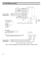
on circuit board (refer to Figure 26). Insert
sensor through hole in circuit board above
terminals marked "ZR" and "L1", see Figure 26,
and into immersion well until it rests against the
bottom of the well as shown in Figure 6.
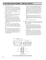
Figure 5A: Relief Valve and Boiler Control
Assembly Details - Beckett AFII Burner
III. PACKAGED BOILER ASSEmBLy - TRIm AND CONTROLS (continued)
2.
Riello BF Burner:
Step a.
Locate the L7248L Boiler Control/
Transformer - Relay Control Center/Harness
Assembly in the carton secured to shipping skid.
Loosen mounting clamp screw on front of
L7248L Control. Mount Control on factory
installed immersion well located in center
tapping on top of boiler with L7248L Boiler
Control/Transformer - Relay Control Center/
Harness Assembly on the left hand side as shown
in Figure 5B.
Step b.
Remove Transformer - Relay Cover from
Junction Box. Locate (2) #8 x 1/2" sheet metal
screws (SMS) and (1) 5/8" cable clamp in parts
bag. Use #8 x 1/2" SMS to secure Junction Box
to pre-punched holes in top panel. Replace
Transformer - Relay cover. See Figure 5B.
Step c.
Locate burner swing door disconnect
harness wrapped around burner air tube. Un-
ravel harness and route to transformer/relay
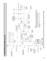
terminals and show in Figures 1B and 5B.
Connect forked convectors to terminals "R" and
"G" on top of transformer as shown in Figure
15B.
Step d.
Remove burner cover. Secure burner
harness to knockout located in lower right corner
on burner cover back plate.
Step e.
Attach wires from burner harness to
terminals on Primary Control per Figure 12.
Step f.
Secure burner harness to burner back plate
with 5/8" cable clamp and existing top screw in
back plate. DO NOT tighten top screw fully
until cover is replaced.
Step g.
Replace burner cover and tighten (3)
retainer screws.
Step h.
Locate the aquastat sensor inside L7248
Boiler Control. Carefully connect sensor into the
L7248 Boiler Control circuit board by pressing
connector on sensor unit into mating connector
on circuit board (refer to Figure 26). Insert
sensor through hole in circuit board above
terminals marked "ZR" and "L1", see Figure 26,
and into immersion well until it rests against the
bottom of the well as shown in Figure 6.
Summary of Contents for LE DV Series
Page 5: ...5 I General Information Figure 1A LEDV Packaged Water Boiler with Beckett AFII Burner ...
Page 6: ...6 I General Information continued Figure 1B LEDV Packaged Water Boiler with Riello BF Burner ...
Page 19: ...19 v venting continued Figure 11 Vent Installation Figure 12 Vent Connector Un Assembled ...
Page 20: ...20 v venting continued Figure 13 Vent Connector Assembled Figure 14 Air Intake Installation ...
Page 48: ...48 xiii Repair Parts continued Figure 29 LEDV Bare Boiler Assembly ...
Page 50: ...50 xiii Repair Parts continued Figure 30 LEDV Boiler Jacket Insulation ...
Page 55: ...55 xiii Repair Parts continued Figure 33 Vent Kit Repair Parts ...
Page 60: ...60 U S Boiler Company Inc P O Box 3020 Lancaster PA 17604 1 888 432 8887 www usboiler net ...

