41
XI. BOILER CLEANING
NOTICE
BURNER SHUTDOWN: Open Service Switch
to turn off burner.
manual Oil Supply Valve should be closed
and Electric Service to boiler turned off.
A
.
General
. Inspection, service and cleaning should be
conducted annually. Turn off electric power and close
oil supply valve while conducting service or
maintenance.
B.
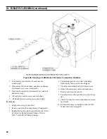
CLEAN THE FIRETUBES, see Figure 28.
1. For access to fireside of boiler, separate two halves
of Burner Swing Door Interlock wiring harness
apart. Remove screws securing burner harness cable
clamps to jacket right side panel. Remove 5/16" -18
x 3" lg. cap screws and washers holding door closed.
2. To OPEN Burner Swing Door Fully, raise burner
harness over top edge of door. If burner is equipped
with flexible fuel line(s), swing door open.
3. It is NOT necessary to remove the vent connector
from the smoke box to clean boiler. If necessary,
remove the vent connector if there is evidence of
heavy soot accumulation in the boiler or to inspect
base of chimney for condensate or accumulation of
debris.
4. Prior to cleaning boiler, lay a protective cloth or
plastic over combustion chamber liner.
5. Using a 1 1/2" diameter wire brush (30" handle) to
clean firetubes. Measure 15" from end of brush
opposite handle, and mark handle. DO NOT allow
this mark to go past front end of firetube during
cleaning, or brush will hit rear door insulation piece.
C.
CLEAN THE COMBUSTION CHAMBER, see
Figure 28.
Using wire or fiber bristle brush, clean inside of
combustion chamber. DO NOT let brush hit rear door
insulation piece or combustion chamber liner.
D.
AFTER CLEANING
Vacuum debris inside bottom of rear door, remove
protective cloth, and vacuum remaining fireside of
boiler as necessary. BE CAREFUL not to damage liner
or rear door insulation piece. Inspect front and rear door
insulation pieces, front door gaskets and combustion
chamber liner for damage. Replace any damaged pieces
immediately.
E.
CLOSE AND SECURE BURNER SWING DOOR.
CAUTION:
Do not start burner unless burner swing door is
securely closed. Close door, install 5/16" -18 lg. cap
screws and washers, and tighten securely. Door should
be parallel to tubesheet when viewed from top and
sides. Reconnect two halves of Swing Door Interlock.
F.
Vent/Air Intake System.
Inspect for obstructions, soot
accumulation, proper support, and deterioration of pipe,
fittings, and joints.
1. Inspect inside of vent pipe.
a. Disconnect appliance adapter from boiler flue
collar.
b. Remove any obstructions and clean with a wire
brush as required.
c. Reconnect appliance adapter to boiler flue collar
as detailed in Section V: Venting/Air Intake
Piping.
2. Clean terminal screens. Terminals must be free of
obstruction, undamaged, with screens securely in
place.
WARNING
All boiler cleaning must be completed with burner service switch turned off. Boilers equipped with burner
swing door have a potential hazard which can cause severe property damage, personal injury or loss of
life if ignored. Before opening swing door, turn off service switch to boiler to prevent accidental firing of
burner outside the combustion chamber. Before opening burner swing door, separate two halves of burner
swing door interlock wiring harness. Be sure to tighten swing door fastener completely when service is
completed.
WARNING
This boiler must be properly vented and connected to an approved vent system in good condition. DO
NOT operate boiler with the absence of an approved vent system.
The interior of the venting and air intake systems must be inspected and cleaned before the start of the
heating season and should be inspected periodically throughout the heating season for any obstructions.
Clean and unobstructed venting and air intake systems are necessary to allow noxious fumes that could
cause injury or loss of life to vent safely and will contribute toward maintaining the boiler's efficiency.
Summary of Contents for LE DV Series
Page 5: ...5 I General Information Figure 1A LEDV Packaged Water Boiler with Beckett AFII Burner ...
Page 6: ...6 I General Information continued Figure 1B LEDV Packaged Water Boiler with Riello BF Burner ...
Page 19: ...19 v venting continued Figure 11 Vent Installation Figure 12 Vent Connector Un Assembled ...
Page 20: ...20 v venting continued Figure 13 Vent Connector Assembled Figure 14 Air Intake Installation ...
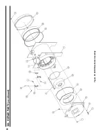
Page 48: ...48 xiii Repair Parts continued Figure 29 LEDV Bare Boiler Assembly ...
Page 50: ...50 xiii Repair Parts continued Figure 30 LEDV Boiler Jacket Insulation ...
Page 55: ...55 xiii Repair Parts continued Figure 33 Vent Kit Repair Parts ...
Page 60: ...60 U S Boiler Company Inc P O Box 3020 Lancaster PA 17604 1 888 432 8887 www usboiler net ...


