57
APPENDIX A: LOW WATER CUT OFF (LWCO) ON HOT WATER BOILERS
(continued)
A 24 VAC LWCO is used primarily for gas fired boilers
where a 24 volt control circuit exists within the boiler.
However, a 24 VAC LWCO can only be used if the
boiler manufacturer has provided piping and wiring
connections and instructions to allow for this
application.
How to Test
Shut off fuel supply. Lower water level until water
level is BELOW the LWCO. Generate a boiler demand
by turning up thermostat. Boiler should not attempt to
operate. Increase the water level by filling the system.
The boiler should attempt to operate once the water
level is above the LWCO.
APPENDIX B: FIGURES
Figure
Number
Page
Number
Description
Section I - General Information
Figure 1A
5
LEDV Packaged Water Boiler with Beckett AFII Burner
Figure 1B
6
LEDV Packaged Water Boiler with Riello BF Burner
Section II - Pre-Installation
Figure 2
8
Minimum Installation Clearances To Combustible Materials
Figure 3
9
Legs Secured to Skid
Section III - Packaged Boiler Assembly - Trim and Controls
Figure 4
10
Hinge Installation & Assembly, LEDV Boiler
Figure 5A
11
Relief Valve and Boiler Control Assembly Details - Beckett AFII Burner
Figure 5B
12
Relief Valve and Boiler Control Assembly Details - Riello BF Burner
Figure 6
12
Limit Sensor Insertion
Section IV - Water Piping and Trim
Figure 7
13
Recommended Piping for Combination Heating and Cooling (Refrigeration) System
Figure 8A
14
Recommended Water Piping for Circulator Zoned Heating Systems - Supply Side Circulator
Figure 8B
15
Recommended Water Piping for Zone Valve Zoned Heating Systems - Supply Side Circulator
Section V - Venting
Figure 9
17
Vent Terminal Location
Figure 10
18
Intake Terminal Location
Figure 11
19
Vent Installation
Figure 12
19
Vent Connector, Un-Assembled
Figure 13
20
Vent Connector, Assembled
Figure 14
20
Air Intake Installation
Section VI - Electrical
Figure 15A
24
Schematic Wiring Diagram, Cold Start Control with Beckett AFII Burner
Figure 15B
25
Schematic Wiring Diagram, Cold Start Control with Riello BF Burner
Figure 16
26
Schematic Wiring Diagrams For All Burner Options w/Various Oil Primary Controls
Summary of Contents for LE DV Series
Page 5: ...5 I General Information Figure 1A LEDV Packaged Water Boiler with Beckett AFII Burner ...
Page 6: ...6 I General Information continued Figure 1B LEDV Packaged Water Boiler with Riello BF Burner ...
Page 19: ...19 v venting continued Figure 11 Vent Installation Figure 12 Vent Connector Un Assembled ...
Page 20: ...20 v venting continued Figure 13 Vent Connector Assembled Figure 14 Air Intake Installation ...
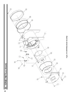
Page 48: ...48 xiii Repair Parts continued Figure 29 LEDV Bare Boiler Assembly ...
Page 50: ...50 xiii Repair Parts continued Figure 30 LEDV Boiler Jacket Insulation ...
Page 55: ...55 xiii Repair Parts continued Figure 33 Vent Kit Repair Parts ...
Page 60: ...60 U S Boiler Company Inc P O Box 3020 Lancaster PA 17604 1 888 432 8887 www usboiler net ...


