31
VIII. SySTEm START-UP (continued)
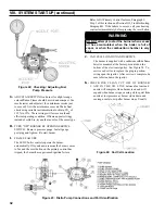
Figure 19: Electrode Tip Gap & Spacing
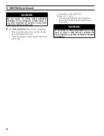
WARNING
Very hot flue gases come out of sight hole when
boiler is operated without sight plug installed.
Always wear proper eye protection.
F.
CHECK / ADJUST OIL PRESSURE
WARNING
DO NOT
loosen or remove any oil line fittings
while burner is operating.
1. Open vent fitting on fuel pump.
2. PRESS RED RESET BUTTON on primary control,
hold for one (1) second and release to reset primary
control.
3. TURN ‘ON’ BURNER service switch and allow
burner to run until oil flows from vent fitting in a
SOLID stream without air bubbles for approximate-
ly 10 seconds.
NOTE:
For Primary Control "Pump Priming
Cycle" details, see Paragraph L, No. 2., Step a.,
Item
ii
.
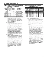
Figure 20: Riello Electrode Setting
Figure 21: Riello Turbulator Setting
4. Close vent fitting and burner flame should start
immediately after prepurge is completed. Prepurge
prevents burner flame until 15 seconds has elapsed
after initial power is applied to burner. During
prepurge the motor and igniter will operate but the
oil valve will remain closed. Refer to Oil Primary
Control Instructions for more details.
5. Adjust oil pressure.
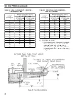
a. When checking a fuel unit's operating pressure, a
reliable pressure gauge may be installed in either
the bleeder port or the nozzle port. For Beckett
burner refer to Figure 22. Refer to Figure 23 for
Riello burner.
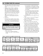
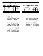
b. Locate oil pressure adjusting screw and turn
screw to obtain proper pump pressure, refer to
Tables 6 and 7.
c. To check the cut-off pressure, deadhead a
reliable pressure gauge onto the copper connec-
tor tube attached to the nozzle port. Run the
burner for a short period of time. Shut the burner
off. The pressure should drop and hold.
d. Turn "OFF" the burner. Remove the pressure
gauge and install port/bleeder plug and/or
reconnect the nozzle port line and tighten. Start
the burner again.
Summary of Contents for LE DV Series
Page 5: ...5 I General Information Figure 1A LEDV Packaged Water Boiler with Beckett AFII Burner ...
Page 6: ...6 I General Information continued Figure 1B LEDV Packaged Water Boiler with Riello BF Burner ...
Page 19: ...19 v venting continued Figure 11 Vent Installation Figure 12 Vent Connector Un Assembled ...
Page 20: ...20 v venting continued Figure 13 Vent Connector Assembled Figure 14 Air Intake Installation ...
Page 48: ...48 xiii Repair Parts continued Figure 29 LEDV Bare Boiler Assembly ...
Page 50: ...50 xiii Repair Parts continued Figure 30 LEDV Boiler Jacket Insulation ...
Page 55: ...55 xiii Repair Parts continued Figure 33 Vent Kit Repair Parts ...
Page 60: ...60 U S Boiler Company Inc P O Box 3020 Lancaster PA 17604 1 888 432 8887 www usboiler net ...


