SERVICE LEVEL MAINTENANCE
TM
44
85809
MANIFOLD WIRING HARNESS
(See Figure 26)
The manifold wiring harness provides electrical
connections for the manifold valve block (solenoids
S1, S2, PF1 and PF2), the electronic control box cable,
the CAN receiver, and the engine including the throttle
control relay and throttle control electromagnet.
TO AVOID DAMAGE TO THE ELECTRICAL
SYSTEM,
Disconnect The Electrical Power To The Hand
Held Control Box Wiring Harness Before
Disassembling The Box.
Electrical power is only present in the system (harness)
when the engine ignition key is in the “ON” or “START”
positions. When the engine ignition key is in the “OFF”
position, no electrical power will be available to complete
the circuits.
Power Wire and Fuse
● Electrical power to operate the 1540 EC circuits is
provided by the positive (
+
) wire that is attached to
terminal “B” on the engine ignition switch. The wire
will only have voltage (
+
) present when the ignition
switch key is in the “ON” position and “Start” position
and the fuse is good.
● The power wire has an in-line fuse holder. Check the
fuse, the proper size is 10 AMP, type ATO.
Manifold Valve Block Wires
(S1, S2, PF1 and PF2 Solenoids)
● The connector at the end of the harness (with wires
labeled dump and ground) plugs into solenoid S1.
The dump wire is positive (
+
) and routes back to the
pin 3 in the gray CAN receiver connector.
● The connector at the end of the harness (with wires
labeled dump and ground) plugs into solenoid
S2. The dump wire is positive (
+
). The wire dump
routes back to the pin 4 in the gray CAN receiver
connector.
● The connector at the end of the harness (with a blue
cap and wires labeled Prop and ground) plugs into
WARNING
CAUTION
solenoid PF1. The dump wire is positive (
+
). The
wire dump routes back to the pin 4 in the gray CAN
receiver connector.
● The connector on the end of the harness (with a
blue a cap and wires labeled Prop and ground)
plugs into solenoid PF2. The dump wire is positive
(
+
). The wire dump routes back to the pin 4 in the
gray CAN receiver connector.
● The wires in these connectors labeled “Ground” are
all negative (
-
) and provide ground for the solenoids.
The ground wires route back into the harness,
are joined to other ground wires and attach to the
common ground point on the 1540 EC frame.
The electronic control box switch must be in the “ON”
position (for both the conveyor belt and the spinner
assembly) and engine ignition key in the “ON” position
to test for voltage at solenoid coils S1, S2, PF1 and PF2.
During operation, when the solenoids are activated,
they close the valves allowing hydraulic flow to power
the hydraulic motors (S1 and S2) and to control their
speeds (PF1 and PF2). No electrical power is present
at the solenoid coils when the control box switch is in
the “OFF” position.
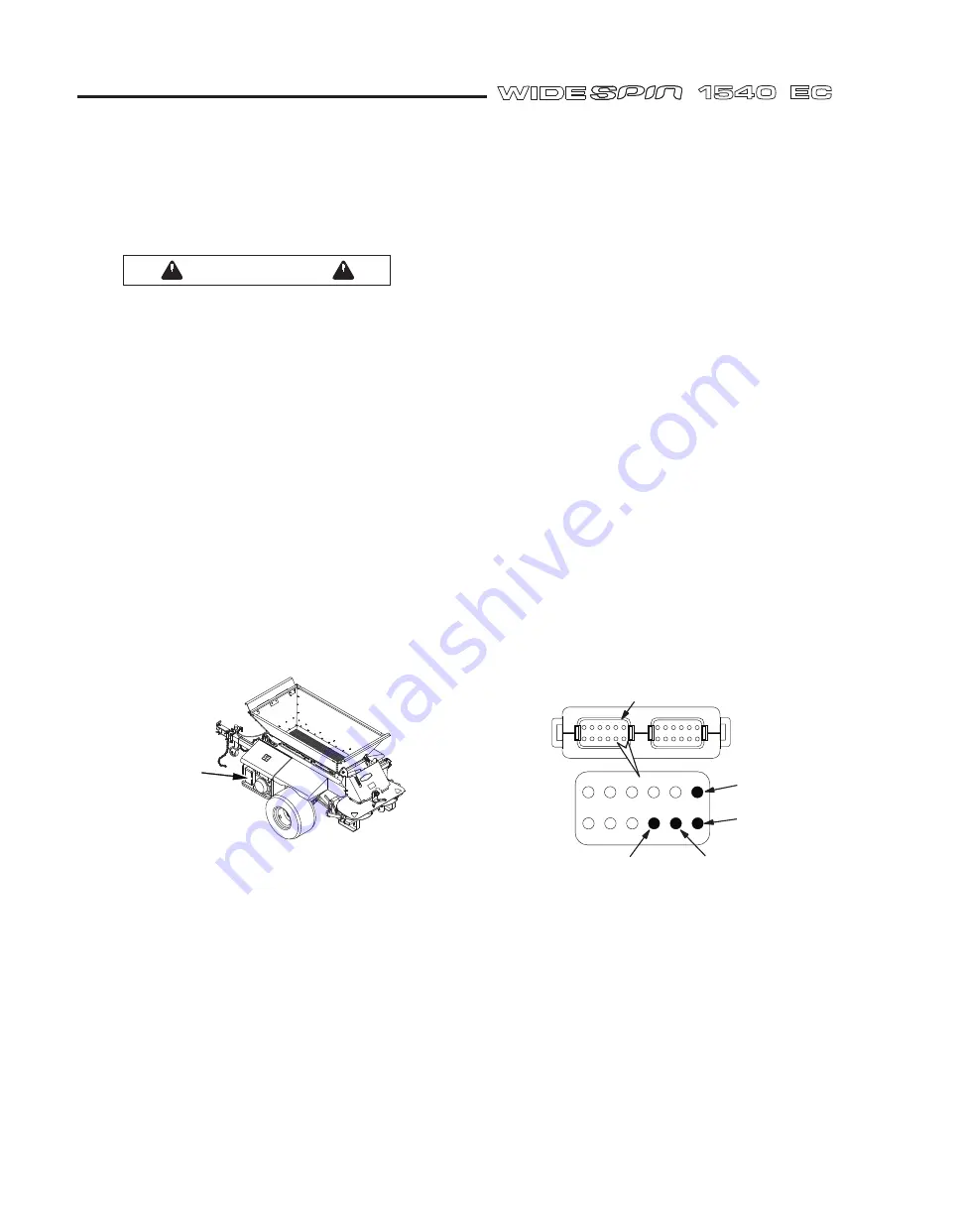
CAN Receiver Wires
The CAN receiver has two connectors, one gray and
one black.
Gray Connector:
the four wires in the gray connector
are for signals and power going into the CAN receiver.
● The wire in Pin 12 labeled “POWER” is electrical
power to operate the CAN receiver circuits is
provided by the positive (
+
) wire. The wire will only
have voltage (
+
) present when the ignition switch
key is in the “ON” position and “Start” position and
the fuse is good.
● The wire in Pin 1 labeled “Ground” is negative (
-
) and
provide ground for the CAN receiver. The ground
wires route back into the harness, is joined to other
ground wires and attach to the common ground
point on the 1540 EC frame.
1
2
3
4
5
6
7
8
9
10 11 12
POWER
GROUND
CAN HIGH
CAN LOW
BOTTOM OF CAN RECEIVER - GRAY CONNECTOR
FIGURE 28
SV85809-22
FIGURE 27
10 AMP FUSE
(UNDER HOOD,
ON WIRE
GOING TO
IGNITION SWITCH)
™
1
5
4
0
E
C
™
SV85809-30


