


TC32306FTG
2015-10-01
46
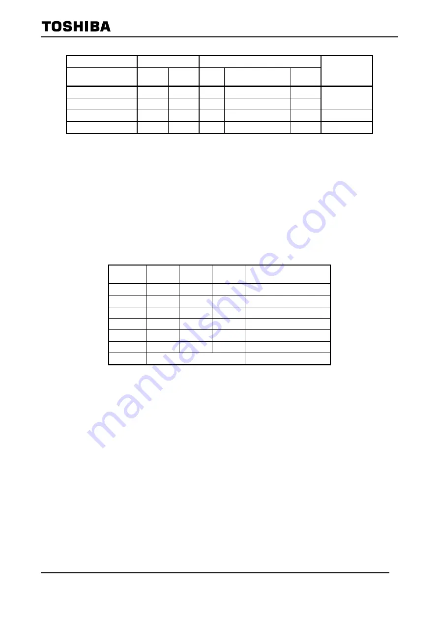
Table 6-47 Status Control in SPI Mode
External Pin
Register Settings
Operations of Function Blocks
Status
ENB Pin
(Only in SPI Mode)
h'0A[D7]
ENB
h'0A[D6]
ACT
SPI
Reference Clock /
Internal Regulator
Others
L
X
X
ON
OFF
OFF
Battery Saving
H
0
X
ON
OFF
OFF
H
1
0
ON
ON
OFF
Standby
H
1
1
ON
ON
ON
Run
X: Don’t care
6.9.1 Power On
à
Battery Saving
à
Run
TC32306FTG will enter the setup sequence after Power On, releasing reset and register settings. In
the setup sequence, this IC starts to setup and operate internal function blocks simultaneously.
- Delay Setting
The setup sequence will start after about 105.5
μ
s (Initial value) from the output level of Reference
Clock Oscillator is over a certain level. Delay is selected by the register setting. Set it with considering
Reference Clock oscillation stabilization time. The start timing of Delay is whichever later that output
level of Reference Clock oscillator will be over a certain level or that TC32306FTG status will move to
Run by the register settings.
Table 6-48 Delay Time Setting of the Setup Sequence Start
h'0D[D7]
Delay_en
h'0D[D6]
Delay2
h'0D[D5]
Delay1
h'0D[D4]
Delay0
Delay time until the setup
sequence starts.
0
X
X
X
105.5
μ
s
1
0
0
0
105.5
μ
s
1
0
0
1
211.1
μ
s
1
0
1
0
316.5
μ
s
1
0
1
1
527.5
μ
s
1
1
0
0
949.5
μ
s
1
Except Above
105.5
μ
s
X: Don’t care
Notice:
-
Delay is derived from 30.32MHz Reference Clock Frequency.
-
In SPI Mode, the initial register setting is h’0D[D7]Delay_en = ”0”. Delay is always about 105.5
μ
s.
-
In SPI Mode, to enter the setup sequence with setting Delay time, move TC32306FTG status
from Battery Saving/Standby to Run after the register setting.
-
If the register of Delay time is set in Run status, the value of Delay time is valid at the next status
moving form Battery Saving/Standby to Run.
-
In EEPROM Mode (Except User Test), this IC enters the setup sequence with the setting Delay
time because this IC status moves from Standby to Run after the register setting.
-
Beware the relationship between supply voltage and reset, when to utilize the power on reset
during boot sequence. (See the notice in 6.3.1)
- Example of Boot Sequence 1: RX (in SPI Mode)
The following Fig 6-29 shows status transition from Battery Saving/Standby to RX-Run.
1.
Power On, then reset is released after the voltage supply becomes stable.
2.
Set registers if necessary with Standby (ENB pin = “H”, register:h’0A[D7]ENB = ”1”,
register:h’0A[D6]ACT = ”0”). Then internal regulators and Reference Clock Oscillator start to
operate.
3.
After the registers settings, set register:h’0A and move to Run.
(ENB pin = “H”, register:h’0A[D7]ENB = ”1”, register:h’0A[D6]ACT = ”1”)