227
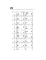
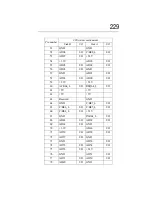
Expansion slots (64bit/66MHz PCI slot)
NOTE: In the table below, “I/O” denotes the input/output
when seen from the server.
Expansion slots (for expansion PCI cards)
Pin number
3.3V-system environment
Side B
I/O
Side A
I/O
1
-12V
TRST_L
O
2
TCK
O
+12V
3
GND
TMS
O
4
TDO
I
TDI
O
5
+5V
+3.3V
6
+5V
INTA_L
I
7
INTB_L
I
INTC_L
I
8
INTD_L
I
+5V
9
PRSNT1_L
I
Reserved
10
Reserved
+3.3V
11
PRSNT2_L
I
Reserved
12
Connector key
Connector key
13
Connector key
Connector key
14
Reserved
Reserved
15
GND
RST_L
O
16
PCICLK
O
+3.3V
17
GND
GNT_L
O
18
REQ_L
I/O
GND
19
+3.3V
Reserved
20
AD31
I/O
AD30
I/O
21
AD29
I/O
+3.3V
22
GND
AD28
I/O
Summary of Contents for Magnia Z300
Page 1: ...MAGNIA Z300 User sGuide ...
Page 4: ...1 2 ...
Page 8: ......
Page 14: ......
Page 22: ...xxii ...
Page 102: ...InstallingandRemovingHardware CPU module 80 Removing the PCI bracket ...
Page 130: ...InstallingandRemovingHardware Expansion cards 108 ...
Page 236: ...Troubleshooting Remedy When Windows NT 2000 is Unusable 214 ...
Page 237: ...Appendix A System Unit 216 External Hard Drive Unit Z1 218 External Device Bay Unit Z1 219 ...
Page 242: ...220 ...
Page 253: ...Appendix C Hardware setup information 232 Recovery Boot 233 ...
Page 257: ...235 Default Jumper Switch Settings PJ47 CMOS Clear PJ723 Recovery Boot ...
Page 258: ...236 ...
Page 259: ...Appendix D ...
Page 270: ...248 ...


