


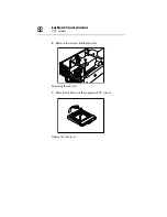


Installing and Removing Hardware
CPU module
84
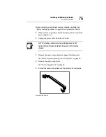
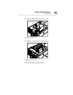
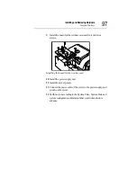
11 Lightly push the heat sink in the direction of the socket, and fix
it by engaging the clips with the upper and lower hooks of the
socket.
Attaching the heat sink
Fixing the clips
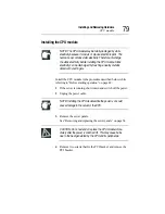
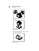
NOTE: Do not push the fin section of heat sink of the CPU
module. This may cause the deformation of the heat sink.
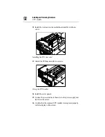
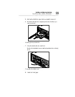
Push the CPU module until both ends of it become uniformly
horizontal on the right and left and confirm that it was inserted
completely.
Summary of Contents for Magnia Z300
Page 1: ...MAGNIA Z300 User sGuide ...
Page 4: ...1 2 ...
Page 8: ......
Page 14: ......
Page 22: ...xxii ...
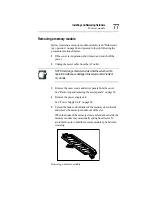
Page 102: ...InstallingandRemovingHardware CPU module 80 Removing the PCI bracket ...
Page 130: ...InstallingandRemovingHardware Expansion cards 108 ...
Page 236: ...Troubleshooting Remedy When Windows NT 2000 is Unusable 214 ...
Page 237: ...Appendix A System Unit 216 External Hard Drive Unit Z1 218 External Device Bay Unit Z1 219 ...
Page 242: ...220 ...
Page 253: ...Appendix C Hardware setup information 232 Recovery Boot 233 ...
Page 257: ...235 Default Jumper Switch Settings PJ47 CMOS Clear PJ723 Recovery Boot ...
Page 258: ...236 ...
Page 259: ...Appendix D ...
Page 270: ...248 ...


