


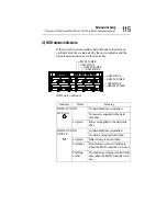


External Unit Setup
Setup of disk array (RAID)
124
NOTE: If the server uses a RAID controller for redundancy,
the operation is continued by a spare disk without stopping
the system, even if one of the hard disk drives that configure
a disk array fails (downgraded operation). However, if
another disk fails, it may destroy and lose important programs
or data. Replace the faulty disk by a normal one as quickly as
possible, and recover the disk array.
Setup of disk array (RAID)
When a RAID controller is additionally installed in the system
after purchase, or it is built in the server before delivery, it is
required to set the disk array (RAID).
When “Simple setup” is selected from the “Selection of RAID
configuration” during execution of the “Setup” of the Toshiba
Server Setup Tool, the RAID controller utilities have no need of
operation because the RAID is configured by minimum setting in
this case. When “Detailed setup” or “No setup” is selected, or the
RAID is to be configured without use of the Toshiba Server Setup
Tool, it is required to set up the RAID.
See “MegaRAID Software Guide”.
If the operating system (OS) is installed in the server in which a
RAID controller is built in, be sure to install a Power Console that
is a RAID monitor and control utility, and the Service after instal-
lation of the OS (for the Windows NT or Windows 2000).
NOTE: When installing the Windows NT or Windows 2000
using the Toshiba Server Setup Tool, the Power Console and
Service can be automatically installed after installation of the
OS.
For installation with the Toshiba Server Setup Tool, see
“Toshiba Server Setup Tool User’s Guide” (on the Documen-
tation CD ROM).
Summary of Contents for Magnia Z300
Page 1: ...MAGNIA Z300 User sGuide ...
Page 4: ...1 2 ...
Page 8: ......
Page 14: ......
Page 22: ...xxii ...
Page 102: ...InstallingandRemovingHardware CPU module 80 Removing the PCI bracket ...
Page 130: ...InstallingandRemovingHardware Expansion cards 108 ...
Page 236: ...Troubleshooting Remedy When Windows NT 2000 is Unusable 214 ...
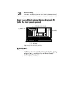
Page 237: ...Appendix A System Unit 216 External Hard Drive Unit Z1 218 External Device Bay Unit Z1 219 ...
Page 242: ...220 ...
Page 253: ...Appendix C Hardware setup information 232 Recovery Boot 233 ...
Page 257: ...235 Default Jumper Switch Settings PJ47 CMOS Clear PJ723 Recovery Boot ...
Page 258: ...236 ...
Page 259: ...Appendix D ...
Page 270: ...248 ...


