*
For additional assistance, please contact Toshiba Adjustable Speed Drive Marketing Dept. at (800) 872-
2192
50
Setpoint via pot on RR terminal: Press LOCAL/REMOTE button to turn green LED off. Make F-CC OR
R-CC (or whatever terminal’s function is set to ‘5’ or ‘0’). Adjust pot to whatever setting it takes to
generate the desired process variable value.
In general,
the setpoint is set up like any frequency reference
(regardless of whether PID is on or not).
For example, to STOP/START from the terminal strip and have a keypad setpoint, Command Mode
Selection must
be set to ‘1’ (terminal input valid) and Frequency Mode Selection must be set to ‘2’ (panel input valid)
just like would have to be done if PID were not being considered.
Feedback Setup
Feedback Input Signal Selection in the FEEDBACK PARAMETERS group tells the drive where to expect
a feedback signal. Program as appropriate. For 10 volt feedback, set to ‘1’. For 4-20 mA feedback, the
default setting ‘2’ is appropriate (set SW1 to ‘I’ position).
Tuning the PID
The idea when tuning this PID is to get fast enough response from the drive that the pressure doesn’t drop
or increase very much. One problem with this is that if the response is too quick, the drive can actually
overshoot (put out a higher frequency than necessary), and in extreme cases, oscillations can occur. The
object then when tuning a PID loop is to
minimize the rise and settling times.
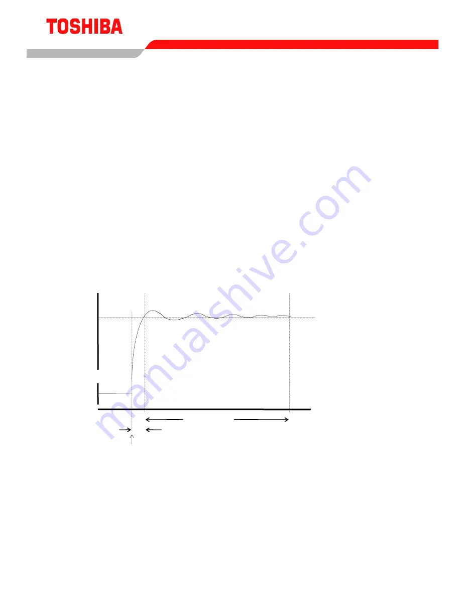
PID Drive Output Hz vs. Time
(in response to pressure drop)
Time
40
Hz
30
Settling
Ti
Rise Time
Time 0
The above figure illustrates what is meant by the rise and settling times. Suppose that a G3 is running at
30 Hz. At Time 0, all of the valves in the example system open. Suppose also that the drive now needs to
speed up to 40 Hz to maintain the desired pressure. The rise time, is the time it takes to go from Time 0
(pressure change) to the needed Hz (for the first time). As seen in the above graph,


