Injection Molding Machine Chapter 7
7-6
V3.0
E
) On charge screen
,
set screw speed at low value 5%
,
adjust flow to min. value to check whether
RPM is less than 10 revolutions
,
then
,
set screw speed at high value 100%
,
adjust flow to max.
value to comply with the highest revolution of hydraulic motor
,
in such a way
,
repeat adjustment
for several times.
F
) On function setting screen
,
set pressure/ speed
,
then based on the value displayed on the
pressure gauge adjust the min./max. pressure values.
G
) Make sure once again that whether the min./max. value of pressure and flow correspond to the
value set.
WARING
The dither frequency of M95PV board has been adjusted with instrument in
factory
,
therefore
,
no adjustment shall be made under any circumstance.
CAUTION
Proportional valve has been adjusted upon factory delivery
,
unless it’s output
linearity is not comply with settings. Do not make any adjustment arbitrarily.
CAUTION
When the linearity isn’t complying with settings
,
please notify service department
for help.
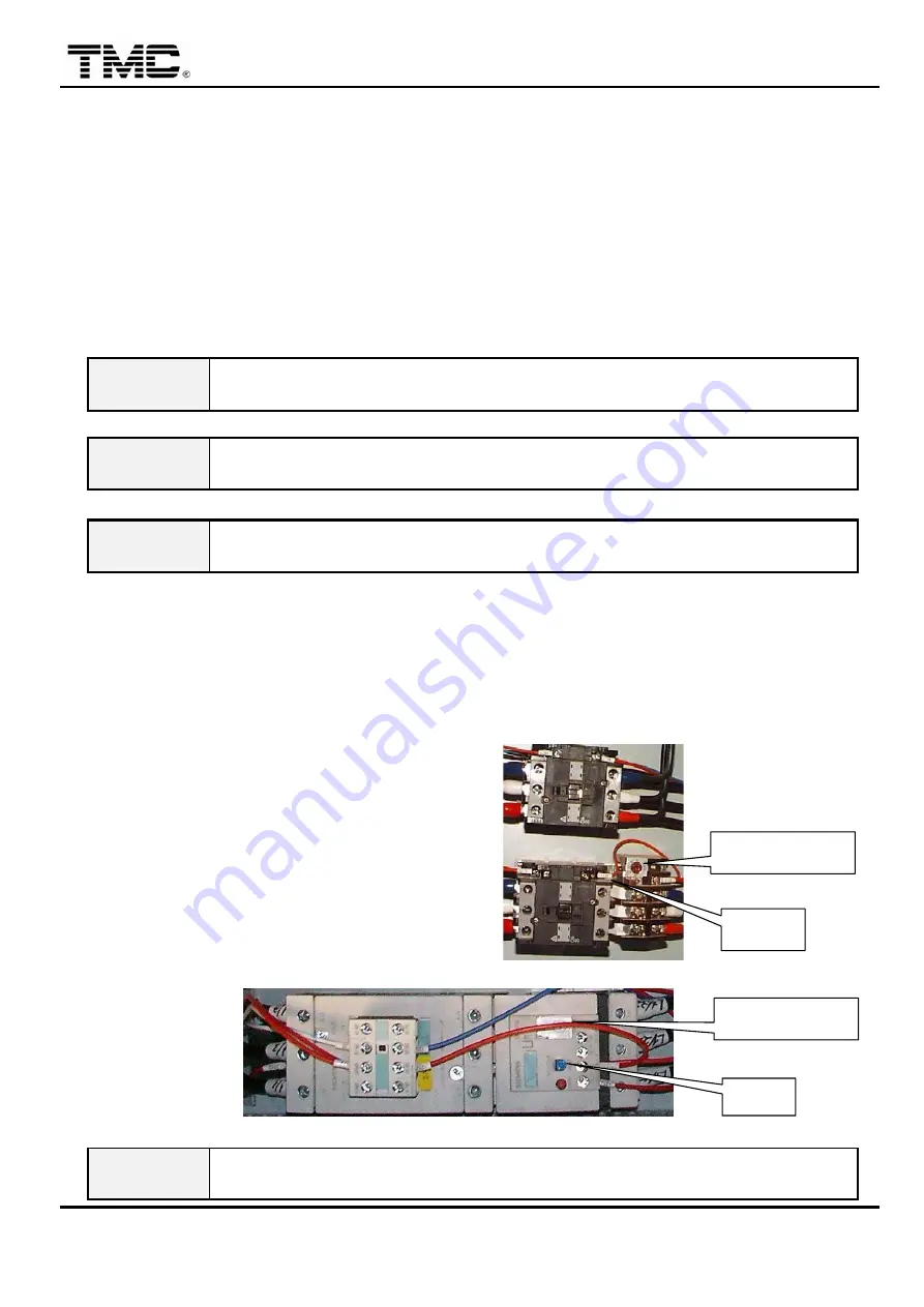
2.3 Adjustment of motor overload protector
(
thermal relay
)
When motor load exceeds the set current
,
motor overload protector will be tripped automatically to
stop motor from operation. At this time
,
the following procedures shall be executed:
A
) Open electric control box door.
B
) Check the set value of current setting
knob for correctness.
C
) Depress RESET bar once
D
) Close electric cabinet door
,
turn power
on.
E
) Depress pump on/off switch to restart the
motor to continue production.
Brand TECO
Brand Siemens
WARING
If improper current is set
(
too high or too low
),
this safety device can not be in
normal operation thus possibly causing motor overheat
,
burned and fire hazards.
R E S E T
C u r r e n t s e t t i n g
C u r r e n t s e t t i n g
R E S E
Summary of Contents for TMC 1000E
Page 20: ...Injection Molding Machine Chapter 2 2 4 V3 0 2 Machine dimensions ...
Page 21: ...Injection Molding Machine Chapter 2 2 5 V3 0 3 Operating position ...
Page 22: ...Injection Molding Machine Chapter 2 2 6 V3 0 4 Safety devices layouts ...
Page 23: ...Injection Molding Machine Chapter 2 2 7 V3 0 5 Position of signs and labels ...
Page 75: ...Injection Molding Machine Chapter 4 V3 0 4 32 starts running to cool down barrel ...
Page 132: ...Injection Molding Machine Chapter 6 V3 0 6 11 4 3 Lubrication points and timing ...
Page 136: ...Injection Molding Machine Chapter 6 V3 0 6 15 32 061 120 3141 Nozzle head S45C PCS 1 ...
Page 149: ...Injection Molding Machine Appendix A A 4 V3 0 1 4 INJECTION INJECTION ...
Page 150: ...Injection Molding Machine Appendix A A 5 V3 0 ...
Page 151: ...Injection Molding Machine Appendix A A 6 V3 0 1 5 CHARGING ...
Page 152: ...Injection Molding Machine Appendix A A 7 V3 0 If CARRIAGE MOVEMENT ON then CARRIAGE RETRACT ...
Page 153: ...Injection Molding Machine Appendix A A 8 V3 0 1 6 CLAMP OPENING ...
Page 159: ...Injection Molding Machine Appendix A A 14 V3 0 1 9 2 GAS VENT SEQUENCE ...
Page 160: ...Injection Molding Machine Appendix A A 15 V3 0 1 9 3 INJECTION COMPRESSION SEQUENCE ...
Page 161: ...Injection Molding Machine Appendix A A 16 V3 0 1 9 4 GAS VENT INJECTION COMPRESSION ...


