231
TIDE and Tibbo BASIC User Manual
©2000-2008 Tibbo Technology Inc.
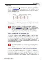
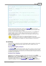
used too (figure B). In case you are building a product that will also accept
input, you may need to control whether the W0&1in input should receive a
logical AND of two lines, or just one of the lines. Schematic diagram C uses an
additional I/O line of the device to control this. When the control line is HIGH the
W0&1in input receives a logical AND of both W0 and W1 lines, when the control
line is LOW, the W0&1in input receives just the signal from the W0 line. Four gates
are required for this, so you will get away with using a single 74HC00 IC.
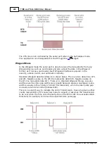
The serial port does not require an incoming Wiegand data stream to adhere to
any strict timing. The port is simply registering high-to-low transitions on the
W0&1in line. When such transition is detected, the port checks the state of W1
line. If the line is HIGH, data bit 0 is registered, when the line is low, data bit 1 is
registered.
The end of Wiegand transmission is identified by timeout- the serial port has a
special property for that, called "intercharacter delay" (see
).
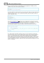
Another property- "auto-close"- can be used to disable the serial port after the
delay has been encountered. This way, when the Wiegand output is over the port
will be disabled and no further data will enter the port until you re-enable it.
232
236

