background image

Servicing 

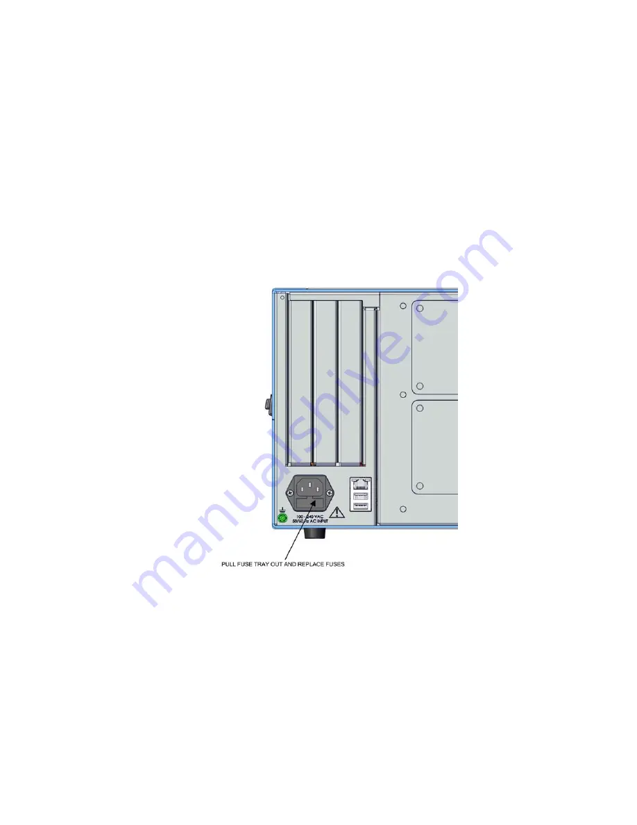
Fuse Replacement 

Thermo Scientific 

49iQ Instruction Manual     

7-5


Use the following procedure to replace the fuses. 

1.


Turn instrument OFF and unplug the power cord. 

2.


Remove fuse drawer, located on the AC power connector. 

3.


If either fuse is blown, replace both fuses. 

4.


Insert fuse drawer and reconnect power cord. 


Figure 7–4.

 Replacing the Fuses 


Fuse 

Replacement

Summary of Contents for 49iQ

Page 1: ...49iQ Instruction Manual Ozone Analyzer 117433 00 1Sep2019 ...

Page 2: ......

Page 3: ...splay 3 1 Main Menus and Keypads 3 5 Numeric Keypad 3 6 Alphanumeric Keypad 3 7 Calibration 3 9 Calibrate Background 3 11 Calibrate Span Coefficient 3 12 Zero Span Schedule 3 14 Custom O3 Levels 3 16 Advanced Calibration 3 17 Manual Calibration 3 18 Calibration History 3 23 Data 3 24 View Data Log Last Hour 3 25 View Data Log Last 24 Hours 3 26 View Data Log User Defined Time 3 27 Advanced Data Se...

Page 4: ...l RS 232 485 3 88 Analog I O 3 89 Digital I O 3 90 Email Server SMTP 3 91 Bayern Hessen Settings 3 92 Instrument Settings 3 94 Display Setup 3 95 Alarm Setpoints 3 96 Clock 3 99 Time Zone 3 103 Configuration 3 106 Security Access Levels 3 107 Change Security to View Only Access 3 109 Change Full Access Security Password 3 110 USB Drive 3 112 Firmware Update Via USB Drive 3 113 Download Data To USB...

Page 5: ...d Span Coef to 1 000 4 17 Zero Span Schedule 4 18 Next Time 4 18 Period 4 18 Zero Span Purge Duration Minutes 4 18 Schedule Averaging Time 4 19 Background 4 19 Zero Span Ratio 4 19 References 4 19 Maintenance 5 1 Safety Precautions 5 1 Fan Filter Inspection and Cleaning 5 1 Pump Rebuilding 5 2 Leak Test 5 5 Optical Bench Cleaning 5 6 Troubleshooting 6 1 Safety Precautions 6 1 Troubleshooting Guide...

Page 6: ...hermistor Replacement 7 37 Scrubber Replacement 7 38 Solenoid Replacement 7 39 Optional DMC Ozonator 7 41 DMC Ozonator Removal 7 41 Lamp Replacement 7 44 Ozonator DMC Board Replacement 7 45 Ozonator Replacement 7 46 Ozonator DMC Install 7 48 Optional Pressure Regulator Replacement 7 50 Optional Manifold Replacement 7 51 System Description 8 1 Photometer DMC with Lamp 8 2 Detector System 8 2 Photom...

Page 7: ...ibration 9 7 Analog Output Full Scale Calibration 9 9 Digital I O Board 9 11 Digital Inputs 9 11 Digital Relay Switches 9 13 Valve Driver Outputs 9 15 Ozonator 9 17 Zero Air Source 9 17 PTFE Particulate Filter 9 17 Safety Warranty and WEEE A 1 Safety A 1 Safety and Equipment Damage Alerts A 1 Warranty A 2 WEEE Compliance A 4 WEEE Symbol A 4 Quick Reference B 1 List of Figures B 1 List of Tables B ...

Page 8: ......

Page 9: ...ing functional performance validation at the module level Built in predictive diagnostics and preventive maintenance schedules identify problems before they occur The iQ Series platform sends email notifications directly to Thermo Fisher Scientific s world class service support team or locally identified addressees in order to proactively communicate analyzer performance conditions and identify sp...

Page 10: ...ries Instrument Platform 1 2 49iQ Instruction Manual Thermo Scientific control mirrors the same GUI look and feel as the instrument touchscreen providing a speedy and familiar operational experience Figure 1 1 49iQ Front ...

Page 11: ...erence source not found One gas stream flows through an ozone scrubber to become the reference gas Io The reference gas then flows to the reference solenoid valve The sample gas I flows directly to the sample solenoid valve The solenoid valves alternate the reference and sample gas streams between cells A and B every 10 seconds When cell A contains reference gas cell B contains sample gas and vice...

Page 12: ...Introduction Principle of Operation 1 4 49iQ Instruction Manual Thermo Scientific Figure 1 2 49iQ Flow Diagram No Sample Cal Valve ...

Page 13: ...Introduction Principle of Operation Thermo Scientific 49iQ Instruction Manual 1 5 Figure 1 3 49iQ Flow Diagram Internal Sample Cal Valve ...

Page 14: ...Introduction Principle of Operation 1 6 49iQ Instruction Manual Thermo Scientific Figure 1 4 49iQ Flow Diagram Internal Ozonator Manifold Sample Cal Valve ...

Page 15: ...Introduction Principle of Operation Thermo Scientific 49iQ Instruction Manual 1 7 Figure 1 5 49iQ Flow Diagram Internal Ozonator Sample Cal Zero Ozone Valves ...

Page 16: ...0 VAC 50 60 Hz 275 Watts Physical Dimensions 24 in D x 16 75 in W x 8 72 in H 609 mm D 425 45 mm W x 221 48 mm H Weight 31 67 lbs std 35 6 lbs with ozonator Analog I O 4 Isolated voltage inputs 0 10 V 6 Isolated analog voltages outputs with 4 selectable ranges 6 Isolated analog current outputs with 2 selectable ranges Digital I O 16 Digital inputs TTL 8 Solenoid driver outputs 10 Digital reed rela...

Page 17: ...Introduction Dimensions Thermo Scientific 49iQ Instruction Manual 1 9 Figure 1 6 Bench Mount Assembly dimensions in inches mm Dimensions ...

Page 18: ...Introduction Dimensions 1 10 49iQ Instruction Manual Thermo Scientific Figure 1 7 Rack Mount Assembly dimensions in inches mm ...

Page 19: ...Introduction Dimensions Thermo Scientific 49iQ Instruction Manual 1 11 Figure 1 8 Rack Mount Requirements Figure 1 9 Rack Requirements Part 2 ...

Page 20: ......

Page 21: ...g container when you receive the instrument notify the carrier immediately and hold for inspection The carrier is responsible for any damage incurred during shipment Use the following procedure to unpack and inspect the instrument 1 Remove the instrument from the shipping container and set it on a table or bench that allows easy access to both the front and rear 2 Remove the cover to expose the in...

Page 22: ... the cover Equipment required Phillips screwdriver 2 1 Unfasten the four 8 32 screws securing the cover shipping screws 2 Press in both latches located on top cover and hold while pulling up to remove Set upright Figure 2 1 Removing the Cover 3 To replace align cover and drop in Latches will automatically snap in place Cover Removing and Replacing ...

Page 23: ...rument can be installed in the following configurations Bench Mount Rack Mount Positioned on bench includes installing feet See Figure 2 2 Equipment required Slot drive 5 16 inch 1 Fasten feet in position 1 or 2 to fit to the desired depth Figure 2 2 Installing Feet Mounting Options Bench Mount ...

Page 24: ...red Phillips drive 2 1 Start by gripping from the top corners of the front panel and pull outwards Figure 2 3 Removing the Front Panel 2 Unfasten the four 8 32 x 3 16 inch pan head screws 3 Slide ears outwards 4 Use the same four 8 32 pan head screws to secure it 5 Install the handles with the four 8 32 flat head screws that came with the handle kit on the backside as shown Rack Mount ...

Page 25: ...Installation and Setup Mounting Options Thermo Scientific 49iQ Instruction Manual 2 5 Figure 2 4 Installing Ears and Handles ...

Page 26: ... be delivered to the instrument at atmospheric pressure It may be necessary to use an atmospheric bypass plumbing arrangement as shown in Figure 2 6 if gas pressure is greater than atmospheric pressure 2 Connect the EXHAUST bulkhead to a suitable vent The exhaust line should be 1 4 inch OD with a minimum ID of 1 8 inch The length of the exhaust line should be less than 10 feet Verify that there is...

Page 27: ...Installation and Setup Setup Procedure Thermo Scientific 49iQ Instruction Manual 2 7 Figure 2 5 49iQ Rear Panel Figure 2 6 Atmospheric Dump Bypass Plumbing ...

Page 28: ...yed on the gas mode button in the title bar and the concentration calculation is turned off To disable warm up go to Settings Configuration 3 Set instrument parameters such as operating ranges and averaging times to their appropriate settings For more information about instrument parameters see the Operation chapter 4 Before beginning the actual monitoring perform a multipoint calibration as descr...

Page 29: ...ser Interface located in the middle is where the Home Screen and all other screens are accessed The Home Screen has three Main Menu buttons located on the left side which include Calibration Data and Settings while the user interface to the right of the buttons displays the chemical name concentration value and unit The Status Bar located at the bottom includes the Back button Access Levels Health...

Page 30: ...Operation Instrument Display 3 2 49iQ Instruction Manual Thermo Scientific Home Screen dual or auto range mode Title Bar User Interface Status Bar ...

Page 31: ...al time status and alarms also predictive diagnostics and maintenance history Contains controls for operating the instrument communications and sets instrument options Concentration When in single mode displays O3 concentrations in big bold characters depending on operating mode When in dual or auto mode displays either high range or low range values based on the range setting Status Bar Back butt...

Page 32: ...Operation Instrument Display 3 4 49iQ Instruction Manual Thermo Scientific Thermo Scientific Information button Shows contact information ...

Page 33: ...s Advanced Measurement Photometer Settings Ozonator Settings Cycle Time Compensation Pressure Calibration Instrument Settings Display Setup Alarm Setpoints Language Clock Pump Power Advanced Instrument Settings Reboot Instrument Communications Configuration Security Access Levels User Contact Information Calibrate Span Coefficient Health Check Status and Alarms Predictive Diagnostics Maintenance F...

Page 34: ...ch as for flow rates temperatures or pressures the keypad screen will automatically display Initially the box above the keypad will display the current value Enter a new value using the keypad and then select the Enter button to set the new value or press the Cancel button to exit the keypad screen and return to the previous screen without saving the value Numeric Keypad ...

Page 35: ...tomatically display Initially the box above the keypad will display the current value Enter a new value using the keypad and then select the Enter button to set the new value or press the Cancel button to exit the keypad screen and return to the previous screen without saving the value The alphanumeric keypad is only available when the user needs to enter alphabet characters Alphanumeric Keypad ...

Page 36: ...Operation Instrument Display 3 8 49iQ Instruction Manual Thermo Scientific ...

Page 37: ... have two O3 span factors high and low This allows each range to be calibrated separately This is necessary if the two ranges used are not close to one another For example a low O3 range of 50 ppb and a high O3 range of 20 000 ppb For more information about range modes see Range Mode Selection on page 3 72 Home Screen Calibration single range mode Home Screen Calibration dual or auto range mode Th...

Page 38: ...te Low Range Span Coefficient Sets the low range span coefficient when in dual or auto range mode Zero Span Schedule Programs the instrument to perform fully automated zero and span checks or adjustments Custom O3 Levels User sets concentration for O3 levels and standby Advanced Calibration Calibrates the instrument using manual zero span calibration and provides calibration history ...

Page 39: ...bilize each time input gas is changed and set the averaging time to 300 second averaging Home Screen Calibration Calibrate Background The Calibrate Background menu contains the following information Target Concentration Read only Displays what the concentration value will become when the calibrate button is pressed Current Background Read only Displays what the current user set background is Calcu...

Page 40: ...icate the calibration of the high or low coefficient The Calibrate High Range Span Coefficient and Calibrate Low Range Span Coefficient screens function the same way It is important to note the averaging time when calibrating The longer the averaging time the more precise the calibration results To achieve maximum precision allow the instrument to stabilize each time input gas is changed and set t...

Page 41: ...t is when in single range mode Current High Range Span Coefficient Displays what the current user set high range span coefficient is when in dual or auto range mode Current Low Range Span Coefficient Displays what the current user set low range span coefficient is when in dual or auto range mode Calculated Span Coefficient Read only After the Edit Span Concentration value is entered the new calcul...

Page 42: ...n Zero Span Schedule Toggles zero span schedule Enabled or Disabled Next Time Allows the user to view and set the initial date and time 24 hour format of the zero span schedule Period Defines the period or interval between zero span checks or calibrations If period 0 the schedule runs continuously Zero Duration Sets how long zero air is sampled by the instrument Ozonator Level 1 6 Duration Sets th...

Page 43: ... a background check only and background value is not updated Span Calibration Toggles Enabled Disabled If enabled span coefficient is calibrated If disabled schedule runs a calibration check only and span coefficient is not updated Zero Span Ratio Allows the user to perform more scheduled background calibration checks to span calibration checks Default is 1 and therefore should read 1 1 This means...

Page 44: ...is screen is only displayed if the ozonator option is installed Use the and buttons to move up and down and the and buttons to move left and right Home Screen Calibration Custom O3 Levels The Custom O3 Levels screen contains the following information Across O3 Levels This column lists items associated with the O3 concentration Value Displays the current value for each item Units Displays units for...

Page 45: ...ration history See Chapter 4 Calibration for further instructions on how to run a calibration Home Screen Calibration Advanced Calibration The Advanced screen contains the following information Manual Calibration The user manually adjusts the background or span coefficient Calibration History Lists all calibrations performed and calibration checks Advanced Calibration ...

Page 46: ...n dual or auto range modes High Range or Low Range buttons are displayed to indicate the calibration of the high or low coefficient Home Screen Calibration Advanced Calibration Manual Calibration single range mode Home Screen Calibration Advanced Calibration Manual Calibration dual or auto range mode The Manual Calibration screen contains the following information Adjust Background Allows the user...

Page 47: ... user to manually adjust the high range span coefficient when in dual or auto range mode Adjust Low Range Span Coefficient Allows the user to manually adjust the low range span coefficient when in dual or auto range mode Reset Background to 0 000 and Span Coefficient to 1 000 Resets all backgrounds and coefficients ...

Page 48: ...ion Advanced Calibration Manual Calibration Adjust Background The Adjust Background screen contains the following information Adjust Background User manually adjusts zero background Adjusted Concentration Read only Shows adjusted concentration based on adjusted zero background Calibrate Calibrates zero background by saving the newly adjusted zero Adjust Background ...

Page 49: ...nt and Adjust Low Range Span Coefficient screens function the same way Home Screen Calibration Advanced Manual Calibration Adjust Span Coefficient single range mode Home Screen Calibration Advanced Calibration Manual Calibration Adjust High Range Span Coefficient dual or auto range mode The Adjust Span Coefficient screen contains the following information Adjust Span Coefficient User manually adju...

Page 50: ...nge concentration based on adjusted high range span coefficient when in dual or auto range mode Adjust Low Range Span Coefficient User manually adjusts low range span coefficient when in dual or auto range mode Adjusted High Range Concentration Read only Shows adjusted low range concentration based on adjusted low range span coefficient when in dual or auto range mode Calibrate Calibrates span coe...

Page 51: ...Calibration History Note Pressing the Calibration History button responds with Retrieving calibration log data it may take a few seconds The Calibration History screen contains the following information Time Stamp Time of calibration or calibration check Event Lists the type of calibration event Result Concentration result Target Concentration setpoint value Units Displays units for each item Aver...

Page 52: ...ollowing information View Data Log Last Hour User views last hour of historical data Table shows most recent data on top View Data Log Last 24 Hours User views 24 hour of historical data Table shows most recent data on top View Data Log User Defined Time User selects the start and end time for viewing the data Table shows most recent data on top Advanced Data Setup Allows the user to set up the pa...

Page 53: ...up and down and the and buttons to move left and right Home Screen Data View Data Log Last Hour Note Pressing the View Data Log Last Hour responds with Retrieving user log data it may take a few seconds The View Data Log Last Hour screen contains the following options Graph Displays data graph for the column selected The graph time axis is defined by the data set in the table View Data Log Last Ho...

Page 54: ...nd down and the and buttons to move left and right Home Screen Data View Data Log Last 24 Hours Note Pressing the View Data Log Last 24 Hours responds with Retrieving user log data it may take a few seconds The View Data Log Last 24 Hours screen contains the following options Graph Displays data graph for the column selected The graph time axis is defined by the data set in the table View Data Log...

Page 55: ... Time Home Screen Data View Data Log User Defined Time Save Data Logging Start Time The View Data Log User Defined Time screen contains the following information Date Sets date of data logging start time Time Sets time of data logging start time Save Data Logging Start Time Pressing this button saves the start time and follows directly to the end time selection for the data logging screen View Dat...

Page 56: ...ation Date Sets date of data logging end time Time Sets time of data logging end time Save Data Logging End Time Pressing the Save Data Logging End Time button saves the end time and follows directly to the data logging table Note End time should not be greater than 1 year from start time Note The datalogging table is limited to 10 000 points ...

Page 57: ...p parameters for data logging and streaming data Home Screen Data Advanced Data Setup The Advanced Data Setup screen contains the following information Data Logging Setup User selects the parameters for collecting logged data Streaming Data Setup User selects the parameters for streaming data to a computer in real time Advanced Data Setup ...

Page 58: ...ariables to log Period User selects how often data is collected by setting the duration between logged data Data Treatment Toggles between Average Current Minimum and Maximum When set to average the average value during the period will be recorded When set to current the latest data will be recorded When set to minimum or maximum the minimum or maximum value during the period will be recorded Eras...

Page 59: ...re exclusive from each other but contain the same variable selections The list is based on the instrument s configuration Use the and buttons to select the variables Next press the Commit Changes button to save selections Yellow buttons indicate that the variable is selected More than one can be chosen Home Screen Data Advanced Data Logging Setup Select Data Logging Variables Select Data Logging V...

Page 60: ...ng Data Setup screen contains the following information Select Streaming Variables User selects which variables to stream Period Sets the time between streamed data Show Labels Toggles enabled disabled When enabled shows variable labels to the right of the variable values Show Timestamp Toggles enabled disabled When enabled shows timestamp at the beginning of each row of data Streaming Data Setup ...

Page 61: ...re exclusive from each other but contain the same variable selections The list is based on the instrument s configuration Use the and buttons to select the variables Next press the Commit Changes button to save selections Yellow buttons indicate that the variable is selected More than one can be chosen Home Screen Data Advanced Streaming Data Setup Select Streaming Variables Select Streaming Varia...

Page 62: ...act Thermo Fisher Scientific technical support Measurement Settings Allows the user to setup user preferences as related to the concentration readings Communications Allows the user to communicate with outside devices Instrument Setting Allows the user to setup alarm setpoints and user preferences Configuration User selects which options to enable Security Access Levels User selects security proto...

Page 63: ...s the following information Status and Alarms Allows the user to view the status and alarm menus Menus are broken down according to modules where the user can view instrument readings setpoints and alarms Predictive Diagnostics Smart module diagnostics which shows possible future issues Maintenance History Allows the user to set up a maintenance schedule and track maintenance history File Sharing ...

Page 64: ...en Note This symbol denotes there is an active alarm in the module Home Screen Settings Health Check Status and Alarms Home Screen Settings Health Check Status and Alarms More The Status and Alarms menu contains the following information Concentration Displays O3 concentration and alarms Photometer Bench Displays photometer bench alarms and faults Ozonator Displays ozonator alarms and faults Inten...

Page 65: ...and faults Peripherals Support Displays peripherals support alarms and faults Valve and Pump Resets User can reset valve and pump power Analog I O Displays analog input output alarms and faults Digital I O Displays digital input output alarms and faults Serial Numbers Displays all the serial numbers for the instrument ...

Page 66: ...ation The Concentration screen contains the following information Across Concentration This column lists items associated with the CO and O2 if applicable concentrations Value Displays the current value for each item Low Alarm Displays low alarm status for each item High Alarm Displays high alarm status for each item Span Conc Span concentration used in the span calibration or span check Units Dis...

Page 67: ...lays concentration based on the last attempted span calibration High alarm shows user defined limit for acceptable span check offset compared to the span concentration value Span concentration shows span setpoint Note If both the low alarm and high alarms are set to zero then no alarm will show ...

Page 68: ...r This column lists items associated with the photometer Value Displays the current value for each item Low Alarm Displays low alarm status for each item High Alarm Displays high alarm status for each item Units Displays units for each item Down Photometer Pressure Displays the current photometer pressure reading Flow Displays the current sample flow reading Bench Temperature Displays the current ...

Page 69: ...s OK Fail for bench temperature sensor short Bench Temp Sensor Open Displays OK Fail for bench temperature sensor open Board Communication Failure Displays OK Fail for board communication status Power Supply Displays OK Fail of power supplies Power supply goes red if any voltages are outside their limits No voltage rows ever get highlighted 2 5 V Diagnostics Displays current voltage readings Alarm...

Page 70: ...ttings 3 42 49iQ Instruction Manual Thermo Scientific 24 0 Volts Displays current voltage readings Alarm limits are not changeable Note If both the low alarm and high alarms are set to zero then no alarm will show ...

Page 71: ...n lists items associated with the ozonator Value Displays the current value for each item Low Alarm Displays low alarm for each item High Alarm Displays high alarm for each item Units Displays units for each item Down Lamp Temperature Displays the current lamp temperature reading User can adjust low and high alarm limits Lamp Temp Sensor Short Displays the OK Fail for lamp temperature sensor short...

Page 72: ...nostic Displays current voltage readings Alarm limits are not changeable 3 3 V Diagnostic Displays current voltage readings Alarm limits are not changeable 5 0 V Diagnostic Displays current voltage readings Alarm limits are not changeable 5 20 V Diagnostic Displays current voltage readings Alarm limits are not changeable 15 V Diagnostic Displays current voltage readings Alarm limits are not change...

Page 73: ... is visible only if the photometer option is installed All intensity screens function the same way Therefore the following example of the Intensity A Reference Gas screen applies to all screens as well Home Screen Settings Health Check Status and Alarms Intensity Check Home Screen Settings Health Check Status and Alarms Intensity Check Intensity A Reference Gas The Intensity Check screen contains ...

Page 74: ...struction Manual Thermo Scientific Intensity B Sample Gas Displays sample gas Cell A Reference Gas Intensity Read only Cell A Reference Gas Noise Read only Cell B Reference Gas Intensity Read only Cell B Reference Gas Noise Read only ...

Page 75: ...l pressure check screens function the same way Therefore the following example of the Sample Pressure screen applies to all screens as well Home Screen Settings Health Check Status and Alarms Pressure Check Home Screen Settings Health Check Status and Alarms Pressure Check Sample Pressure The Pressure Check screen contains the following information Sample Pressure Read only Displays the pressure o...

Page 76: ...e following information Across Flow and Pressure This column lists items associated with the flow and pressure module Value Displays the current value for each item Low Alarm Displays low alarm status for each item High Alarm Displays high alarm status for each item Units Displays units for each item Down Flow Displays the current sample flow reading User can adjust low and high alarm limits Photo...

Page 77: ... if any voltages are outside their limits No voltage rows ever get highlighted 2 5V Diagnostic Displays current voltage readings Alarm limits are not changeable 3 3V Diagnostic Displays current voltage readings Alarm limits are not changeable 5 0V Diagnostic Displays current voltage readings Alarm limits are not changeable 24V Diagnostic Displays current voltage readings Alarm limits are not chang...

Page 78: ... contains the following information Across Peripherals Support This column lists items associated with the peripherals support module Value Displays the current value for each item Low Alarm Displays low alarm status for each item High Alarm Displays high alarm status for each item Units Displays units for each item Down Instrument Temperature Displays the current instrument temperature of the mod...

Page 79: ... 5V Diagnostic Displays current voltage readings Alarm limits are not changeable 3 3V Diagnostic Displays current voltage readings Alarm limits are not changeable 5 0V Diagnostic Displays current voltage readings Alarm limits are not changeable 24V Diagnostic Displays current voltage readings Alarm limits are not changeable 5V Step Board 1 Displays current voltage readings Alarm limits are not cha...

Page 80: ...at the device needs to be reset Home Screen Settings Health Check Status and Alarms Valve and Pump Resets The Valve and Pump Resets screen contains the following information Sample Cal Valve Reset Resets sample cal valve Sample Valve Reset Resets sample valve Reference Valve Reset Resets reference valve Ozonator Solenoid Valve Reset Resets ozonator solenoid valve Pump Reset Resets pump Valve and P...

Page 81: ...contains the following information Across Analog IO This column lists items associated with the analog I O Value Displays the current value for each item Low Alarm Displays low alarm status for each item High Alarm Displays high alarm status for each item Units Displays units for each item Down Voltage Output Channel 1 6 Displays real time voltage output for each channel Current Output Channel 1 6...

Page 82: ...o voltage rows ever get highlighted 3 3V Diagnostic Displays current voltage readings Alarm limits are not changeable 5 0V Diagnostic Displays current voltage readings Alarm limits are not changeable 5 0V Ref Diagnostic Displays current voltage readings Alarm limits are not changeable 15V Diagnostic Displays current voltage readings Alarm limits are not changeable 15V Diagnostic Displays current v...

Page 83: ... the following information Across Digital IO This column lists items associated with the digital I O Value Displays the current value for each item Reset Resets item Low Alarm Displays low alarm status for each item High Alarm Displays high alarm status for each item Units Displays units for each item Down Solenoid 1 8 Displays whether or not the solenoid is activated by showing the current in mA ...

Page 84: ...oes red if any voltages are outside their limits No voltage rows ever get highlighted 3 3V Diagnostic Displays current voltage readings Alarm limits are not changeable 5 0V Diagnostic Displays current voltage readings Alarm limits are not changeable 24V Diagnostic Displays current voltage readings Alarm limits are not changeable ...

Page 85: ...larms More Serial Numbers The Serial Numbers screen contains the following information Instrument Instrument serial number Photometer Photometer serial number Ozonator Ozonator serial number Flow and Pressure Flow and pressure serial number Peripherals Support Peripherals support serial number Analog I O Analog I O serial number Digital I O Digital I O serial number Serial Numbers ...

Page 86: ...ing time If button is greyed out no maintenance is needed If button is blue maintenance is suggested Note This symbol denotes there is an active maintenance related warning in the module Home Screen Settings Health Check Predictive Diagnostics The Predictive Diagnostics screen contains the following information Sample Pump Capillary Flow Path Sample Valve Zero Valve Span Valve Predictive Diagnosti...

Page 87: ... Health Check Maintenance Home Screen Settings Health Check Maintenance Advanced Maintenance The Maintenance screen contains the following information Preventive Maintenance Shows suggested service interval and time left for component replacement Change Part User logs component fix Maintenance History Shows the log of all recorded component fixes Service Tips Provides video and procedural service ...

Page 88: ...reen contains the following information Across Component Device to be routinely serviced or replaced Interval in Months Expected period of time before a component needs to be checked and or serviced Months Left Count down timer in months Remaining time since the beginning of the service interval When the value is 1 or less the row will be highlighted and it is suggested that the component should b...

Page 89: ...erval for lamp heater Flow System Service interval for the flow system components Pump Service interval for pump Capillaries Service interval for capillaries Ozone Scrubber Service interval for ozone scrubber DC Power Supply Service interval for DC power supply Fan Filter Service interval for fan filter System Components Service interval for system components Purafil Service interval for purafil C...

Page 90: ...e diagnostics screen when applicable Home Screen Settings Health Check Maintenance Change Part The Change Part screen contains the following information Select Part User selects part to service from the selection table Fix User chooses from new rebuilt cleaned and unknown Comment User can write a brief comment which will be saved to the preventive maintenance history table Commit User commits and ...

Page 91: ...e and buttons to move up and down and the and buttons to move left and right Home Screen Settings Health Check Maintenance Maintenance History Note Retrieving maintenance history data it may take a few seconds The Maintenance History screen contains the following information Part Component that has been fixed Fix The type of maintenance Date Shows date time when service was logged Service Months A...

Page 92: ...ive Email Health Check Report File to Technical Support Sends the health report file to technical support and the customer email addresses via email Email Health Check Report to Personal Account Sends the health report file to a personal account via email iQ Alert Assistant With the iQ Alert Assistant enabled the instrument will email Thermo Scientific Technical Support the health check report aft...

Page 93: ...ngs Health Check iQ360 Get Started Home Screen Settings Health Check iQ360 Status and Renewal Request The iQ360 screen contains the following information Get Started Allows the user to access the menu where the subscription passcode is entered Status and Renewal Request Allows the user to access the iQ360 menu once the subscription has been enabled Cancel and Return to the Home Screen Exits screen...

Page 94: ...ck iQ360 Get Started The Get Started screen contains the following information Resend Subscription E mail Allows the user to request another subscription passcode if the email was never received Enter Subscription Access Code Allows the user to enter the subscription passcode to enable an iQ360 subscription Exit and Return to the Home Screen Exits screen and returns to the Home Screen Get Started ...

Page 95: ...nd Renewal Request The Status and Renewal Request screen contains the following information iQ360 Status Informs the user if the subscription is enabled iQ360 Subscription Expiration Date Informs the user when the subscription will expire iQ360 Test Connection Allows the user to verify the network connection is working iQ360 Subscription Renewal Allows the user to request a subscription renewal vi...

Page 96: ...uttons averaging buttons will be available Home Screen Settings Measurement Settings single range mode Home Screen Settings Measurement Settings dual or auto range mode The Measurement Setting menu contains the following information Averaging Time Sets the averaging time for the O3 sample measurement Range Mode Selection User can choose between the various range modes single dual or auto For more ...

Page 97: ...e Low Range Setting Sets the low range concentration for the analog output when in dual or auto range mode Gas Mode User can manually choose sample zero or span mode Gas Units Defines the units in which O3 concentration reading is expressed Dilution Ratio Serves as a multiplier when dilution gas is utilized Advanced Measurement Settings Advanced settings affecting O3 readings ...

Page 98: ...me of 300 seconds means that the moving average concentration of the last 300 seconds will be output at each update Therefore the lower the averaging time the faster the front panel display and analog outputs respond to concentration changes Longer averaging times are typically used to smooth output data Dynamic Filtering allows for data smoothing without compromising response time Automatically c...

Page 99: ...bles high range dynamic filtering when in dual or auto range mode Low Range Dynamic Filtering Enables disables low range dynamic filtering when in dual or auto range mode Averaging Time Sets averaging time period in single range mode and when dynamic filtering is disabled High Range Averaging Time Sets high averaging time when in dual or auto range mode and when dynamic filtering is disabled Low R...

Page 100: ... can be set to output concentrations from 0 to 50 ppb and the high O3 analog output set to output concentrations from 0 to 200 ppb In addition each O3 analog output has a span coefficient so that each range can be calibrated separately This is especially necessary if the two ranges are not close to one another For example the low O3 range is set to 0 50 ppb and the high O3 range is set to 0 1 000 ...

Page 101: ...tive the concentration must drop to 85 of the low O3 range for the low range to become active In addition each O3 range and analog output has a span coefficient so that each range can be calibrated separately This is especially necessary if the two ranges are not close to one another For example the low O3 range is set to 0 50 ppb and the high O3 range is set to 0 20 000 ppb ...

Page 102: ... auto range modes The only difference between the screens are the words High or Low displayed to indicate which range is displayed For more information about the dual and auto range modes see Range Mode Selection on page 3 72 Pressing Range Setting High Range Setting or Low Range Setting brings up a numeric keypad whereby the user can select a range Settable ranges according to unit selection incl...

Page 103: ...ome Screen Settings Measurement Settings Gas Mode The Gas Mode screen contains the following information Sample Sets the instrument to measure sample gas Zero Used when calibrating the background of the instrument When pressed sets the instrument to zero mode Level 1 6 Sets the instrument to user defined concentration levels Gas Mode ...

Page 104: ...standard pressure of 760 mmHg and a standard temperature of 0 C The temperature can be changed in the compensation screen Use the and buttons to select Home Screen Settings Measurement Settings Gas Units The Gas Units screen contains the following information ppb parts per billion ppm parts per million percent μg m3 micrograms per meter cubed mg m3 milligrams per meter cubed g m3 grams per meter c...

Page 105: ...easurements Settings menu contains the following information Photometer Bench Settings User can set the detector gain This can be done manually or automatically Ozonator Bench Settings User can run automated calibration for lamp power to concentration Cycle Time Toggles cycle time to either 4 seconds or 10 seconds Compensation Allows the user to compensate for changes in temperature and pressure c...

Page 106: ...ettings Advanced Measurement Settings Photometer Bench Settings Home Screen Settings Measurement Settings Advanced Measurement Settings Photometer Bench Settings Continue to Photometer Bench Settings Screen The Photometer Bench Settings screen contains the following information Across Description Defines the actions the user can do Detector Cal User can manually set or automatically calibrate dete...

Page 107: ...urrent values for detector 2 If detector cal cell is pressed user can manually set the detector 2 cal value Auto Cal When Start is pressed the auto calibration process is initiated Please allow up to 5 minutes for calibration to complete User can stop calibration by pressing the Stop button End Cal When Stop is pressed the auto calibration is interrupted and the value does not change Default Value...

Page 108: ...ent Settings Advanced Measurement Settings Ozonator Bench Settings Home Screen Settings Measurement Settings Advanced Measurement Settings Ozonator Bench Settings Continue to Ozonator Lamp Power to Concentration The Ozonator Lamp Power to Concentration screen contains the following information Across Description Lists items in table Lamp Power to Concentration User can initiate calibration by pres...

Page 109: ...o Cal When Start is pressed the auto calibration process is initiated Please allow up to 60 minutes for calibration to complete User can stop calibration by pressing the Stop button End Cal When Stop is pressed the auto calibration is interrupted and the value does not change ...

Page 110: ...erature variations The effects of internal instrument temperature changes on the analyzer s subsystems and output have been empirically determined This empirical data is used to compensate for any changes in temperature Pressure Compensation Toggles pressure compensation enabled or disabled and provides compensation for any changes to the instrument s output signal due to bench pressure variations...

Page 111: ...sor Calibration Starts calibration or resets default values Down Sensor 1 3 Reading Under the column labeled Reading current reading of each pressure sensor Atmospheric Sensor 1 3 Under the column labeled reading the user enters the current atmospheric pressure in mmHg units Under the column labelled Calibration the user presses the Start button to calibrate the high point of the sensor Zero Senso...

Page 112: ...nstrument through analog I O settings This is only visible if selected in Settings Configuration Analog I O Digital I O Settings for communicating with the instrument through digital I O settings This is only visible if selected in Settings Configuration Digital I O Email Server SMTP Settings for communication with email Instrument ID Allows the user to edit the instrument identification number ID...

Page 113: ...Operation Settings Thermo Scientific 49iQ Instruction Manual 3 85 Note Refer to the Bayern Hessen Protocol section in the Communications Manual for a detailed description ...

Page 114: ...s disabled the static IP address is used Home Screen Settings Communications Wired TCP DHCP with DHCP enabled Home Screen Settings Communications Wired TCP DHCP with DHCP disabled The Wired TCP DHCP screen contains the following information DHCP Toggles DHCP enabled disabled Dynamic IP Address Dynamic IP address of the instrument Dynamic Netmask Dynamic Netmask of instrument Dynamic Gateway Dynami...

Page 115: ...DHCP is disabled Static Netmask Static Netmask of instrument This is settable when DHCP is disabled Static Gateway Static Gateway of instrument This is settable when DHCP is disabled DNS Server Address DNS IP address of instrument This is settable when DHCP is disabled Wired MAC Address Instrument MAC address Host Name Host name of instrument ...

Page 116: ...e Screen Settings Communications Serial RS 232 485 The Serial RS 232 485 screen contains the following information Protocol User selects Streaming Modbus or Bayern Hessen Baud Rate User selectable baud rates from 1200 to 115200 Bits User selectable between 7 and 8 Parity User selectable between None Even and Odd Stop Bits User selectable between 1 and 2 RS 232 485 User selectable between RS 232 an...

Page 117: ... Analog In Allows the user to view and calibrate voltage inputs from external devices Analog Out Voltage Allows the user to view voltage outputs Analog Out Current Allows the user to view current mA outputs Analog Out Under Over Range Enabled Disabled Allows the user to select whether or not the analog outputs are allowed to exceed the selected output range Analog Out Calibration Allows the user t...

Page 118: ...Digital I O Home Screen Settings Communications Digital I O The Digital I O screen contains the following information Digital In Allows the user to view digital inputs from external devices Digital Out Relays Allows the user to view relay outputs Digital Out Solenoids Allows the user to view solenoid outputs Advanced Digital I O Allows user to test the digital out relays and solenoids Digital I O ...

Page 119: ...erver SMTP The Email Server SMTP screen contains the following information SMTP Server Address Address of the user s email server From Email Address The email address that goes in the From field in emails SMTP Server Port Server port of user s email server Email Password Password for SMTP server Email UserName User name that is authorized to send email through SMTP server Email Server SMTP ...

Page 120: ...egisters that will be read with a valid data query DA command Home Screen Settings Communications Bayern Hessen Settings The Bayern Hessen Settings screen contains the following information Register 1 8 Sets the measured value logged in the respective register location in response to a valid query DA command Bayern Hessen Settings ...

Page 121: ...rs corresponding to each measured value appearing after the register name in the selection will preface the measured value in the response to the DA command Use the and buttons to scroll through the registers Select the variable to log by pressing the corresponding cell The list is based on the instrument s configuration Home Screen Settings Communications Bayern Hessen Settings Register 1 8 Regis...

Page 122: ...creen Settings Instrument Settings The Instrument Settings screen contains the following information Display Setup Sets touchscreen display settings Alarm Setpoints View and set all available alarm setpoints Language Sets language Clock Sets date and time Pump Power Manually enables disables the pump Reboot Instrument Reboots the instrument Instrument Settings ...

Page 123: ... save option Home Screen Settings Instrument Settings Display Setup The Display Setup screen contains the following information Power Save Minutes before screen times out Toggles enabled disabled Power Save Setting Option whereby the user can display a black screen after a set amount of inactivity Brightness Sets the brightness of the display Display Setup ...

Page 124: ...reen See Status and Alarms on page 3 36 Use the and buttons to move up and down and the and buttons to move left and right Home Screen Settings Instrument Settings Alarm Setpoints The Alarm Setpoints screen contains the following information Across Variable Lists the items that have settable alarm limits Value Displays the current value for each item Low Alarm User sets low alarm for item High Ala...

Page 125: ...tion checks This is set with the high alarm only Photometer Bench Temp Photometer bench temperature alarm Photometer Pressure Photometer temperature alarm Flow Flow pressure alarm Cell A Intensity Cell A intensity alarm Cell B Intensity Cell B intensity alarm Photometer Lamp Temp Photometer lamp temperature alarm Photometer Lamp Current Photometer lamp current alarm ...

Page 126: ...on Manual Thermo Scientific The Language screen allows the user to choose from the following languages Home Screen Settings Instrument Settings Language The Language screen contains the following information English Chinese Spanish Language ...

Page 127: ...me zone and time server Home Screen Settings Instrument Settings Clock The Clock screen contains the following information Date User sets date Date Format User selects date format Time User sets time Time Zone User chooses time zone Time Server User can enable disable the time server to get periodic clock updates Commit When pressed clock settings are saved Clock ...

Page 128: ... 3 100 49iQ Instruction Manual Thermo Scientific The Date screen allows the user to choose date Use the and buttons to move left and right to select month and year Home Screen Settings Instrument Settings Clock Date Date ...

Page 129: ...the user to choose from the following formats mm dd yyyy or dd mm yyyy Use the and buttons to select Home Screen Settings Instrument Settings Clock Date Format The Date Format screen contains the following information U S Format mm dd yyyy European Format dd mm yyyy ISO 8601 yyyy mm dd Date Format ...

Page 130: ...entific The Time screen allows the user to choose from the following formats mm dd yyyy or dd mm yyyy Use the and buttons to select Home Screen Settings Instrument Settings Clock Time The Time screen contains the following information Hours Minutes Seconds Time ...

Page 131: ...nt Settings Clock Time Zone The Time Zone screen contains the following information Date Line West UTC 12 Samoa Time Zone UTC 11 Aleutian Time Zone UTC 10 Alaskan Time Zone UTC 9 Pacific Time Zone UTC 8 Pacific Daylight Savings UTC 7 Mountain Time Zone UTC 7 Mountain Daylight Savings UTC 6 Central Time Zone UTC 6 Central Daylight Savings UTC 5 Eastern Time Zone UTC 5 Eastern Daylight Savings UTC 4...

Page 132: ...l European Time UTC 1 Eastern European Time UTC 2 Further Eastern European Time UTC 3 Gulf Standard Time UTC 4 Yekaterinburg Time UTC 5 Omsk Time UTC 6 Indochina Time UTC 7 ASEAN Common Time UTC 8 Japan Standard Time UTC 9 Chamorro Time Zone UTC 10 Sredmnekolymsk Time UTC 11 New Zealand Standard Time UTC 12 ...

Page 133: ...iodic clock updates Home Screen Settings Instrument Settings Clock Time Server The Time Server screen contains the following information Time Server Enables Disables periodic clock updates from an NTP Network Time Protocol source Set Time Server User can choose specific time server Set Default When pressed default time server will be used Time Server ...

Page 134: ...elected More than one can be chosen Home Screen Settings Configuration The Configuration screen contains the following information Sample Cal Assembly Enables sample cal assembly option Ozonator Assembly Enables ozonator assembly option Ozonator Standby Enables standby Zero Air Source Enables zero air source option Predictive Diagnostics Enables predictive diagnostics option Communications Board E...

Page 135: ...nly Access The Security Access Levels screen contains the following information Current Security Access Full Access Read only User will be able to change all values Password is needed for full access Current Security Access View Only Read only User won t be able to change any values Password is not needed for view only Change Security Access to View Only User can switch to view only mode Password ...

Page 136: ...Operation Settings 3 108 49iQ Instruction Manual Thermo Scientific Change Full Access Security Password Full access password can have a blank value or user selected password ...

Page 137: ... View Only Access The Change Security to View Only Access screen contains the following information Set Access Level to View Only Programs the instrument to be in the view only access level where the user won t be able to change any values Cancel Exit screen Note To change security access from view only access to full access a keypad will be displayed where the user can enter full access password ...

Page 138: ...curity Password screen allows the user to set a new password for allowing full access Home Screen Settings Security Access Levels Change Full Access Security Password Home Screen Settings Security Access Levels Change Full Access Security Password Continue Change Full Access Security Password ...

Page 139: ...nt security password Continue Proceeds to next screen Enter New Security Access Password User enters new security password Confirm New Security Access Password User confirms new security password for spelling confirmation Commit New Security Access Password Change Commits new security password Cancel and Return to the Home Screen Exits screen and returns to the Home Screen without changing passwor...

Page 140: ... drive is inserted into the USB port When a USB drive is inserted the user is prompted to enter the password if a password has been set Home Screen Settings USB Drive The USB Drive screen contains the following information Firmware Update Via USB Drive If USB is mounted user can update instrument firmware Download Data To USB Drive User can download upload information Change USB Password User can ...

Page 141: ... from the USB drive Home Screen Settings USB Drive Firmware Update Via USB Drive The Firmware Update Via USB Drive screen contains the following information Update Firmware User chooses firmware file from USB and updates instrument firmware Instrument reboots when update is finished Exit User exits without updating firmware Firmware Update Via USB Drive ...

Page 142: ...ncludes a complete listing of data for all variables This is set at the factory Download System Log Consists of system log text files which include a listing of system errors Download Calibration History Includes the data in the calibration history screen Download Configuration Data Backup to USB Allows the user to download the configuration file from the instrument to the USB Upload Configuration...

Page 143: ... the USB connection 1 Plug a flash drive into the USB connection on the front of the instrument If a USB password has been previously set you will be prompted to enter the USB password to continue Press Enter to continue 2 To continue select the OK button 3 The USB Drive will display Select Download Data To USB Drive ...

Page 144: ...transferring data to the USB drive Note Do not remove the USB drive from the instrument while the data is downloading 6 When the data download is complete the instrument will display a Success message and display the file name as it is stored on the USB flash drive The file name format is the instrument serial number name of download followed by a date time stamp Remove the USB flash drive and sel...

Page 145: ...Manual 3 117 The Change USB Password screen allows the user to set a new password for accessing USB Home Screen Settings USB Drive Change USB Password Home Screen Settings Security Access Levels Change Standard Access Password Continue Change USB Password ...

Page 146: ...rs current USB password Continue Proceeds to next screen Enter New USB Password User enters new USB password Confirm New Security Access Password User confirms new security password for spelling confirmation Commit New USB Password Change Commits new USB password Cancel and Return to the Home Screen Exits screen and returns to the Home Screen without changing password ...

Page 147: ...ls found at the screen Health Check File Sharing and Support Home Screen Settings User Contact Information The User Contact Information screen contains the following information Business Name User Name Alternate User Name User ID Business Address Business Shipping Address To User Email Address CC User Email Address 1 10 User Phone Number Alternate User Phone Number Shelter Lab Phone Number User Co...

Page 148: ...ns our operating system on power up The bootloader may change to optimize hardware settings or if there are changes to the hardware If the button is blue an update to the bootloader is available If button is greyed out no update is needed Home Screen Settings Update Bootloader The Update Bootloader screen contains the following information Reboot and Update Update bootloader and reboot instrument ...

Page 149: ... either from compressed cylinders or from scrubbed ambient air If cylinder air is used it should be actual and not synthetic If ambient air is used the following compounds must be removed ozone nitric oxide nitrogen dioxide sulfur dioxide and hydrocarbons The following scheme is recommended by the EPA in its technical assistance document 1 Irradiate the air with an ozone generating UV lamp to conv...

Page 150: ...ifold a photometer and a source of zero air is required The Thermo Scientific 49iQ Ozone Photometric Primary Standard satisfies the calibration photometer system requirement in a single convenient package In addition the 49iQ can be modified to operate as a calibration photometer by removing the ozone scrubber and plumbing zero air into the common port of the ozone free solenoid valve as shown in ...

Page 151: ...alibrator to ensure the accuracy of the measurements These tests include System check Ozone loss test Linearity check Intercomparability A step by step checkout procedure to verify proper operation of a 49iQ Primary Standard or a 49iQ modified as described earlier is as follows 1 Turn the calibration photometer ON 2 Turn the ozonator ON 3 Allow the calibration photometer and ozonator to stabilize ...

Page 152: ... as R a input Press the button to return to the Intensity Check screen 6 Connect the calibrated ozone analyzer to the access port on the inlet of cell B From the Intensity Check menu press Intensity A Reference Gas Wait for a steady reading and record the intensity as R b input 7 Replace access fittings used in steps 4 and 6 above and make sure they are leak tight 8 Connect the calibrated ozone an...

Page 153: ...ight sampling the high level of ozone Then repeat ozone loss test Since the 49iQ is inherently linear over the range of interest 0 1 ppm a linearity test is an effective overall test that the instrument is operating properly The checks above should identify whether any causes of non linearity are present The possible causes of non linearity are Dirty or contaminated cell lines or manifold Inadequa...

Page 154: ...e complete and accurate 1 With the ozone generator in the manual mode i e gain set to zero adjust ozone level to generate a level in excess of 0 5 ppm Wait until ozone concentration is stable 2 From the Home Screen press Settings Health Check Status and Alarms Intensity Check From the Intensity Check menu select Intensity A Reference Gas Wait for stable frequency reading and note as Io A Press the...

Page 155: ... intercomparability test of a 49iQ Primary Standard it may be necessary to have the 49iQ Primary Standard sample ozone from a source other than the one contained in the instrument Use the following procedure to accomplish this 1 Set gas mode to zero 2 At the PTFE distribution manifold disconnect the line from the ozonator to the manifold and cap fitting 3 Cap bulkhead labeled VENT 4 Connect PTFE l...

Page 156: ... follow the checkout procedure given in the Manual for the calibration photometer or follow the procedure in the Technical Assistance Document To generate data of the highest confidence it is recommended that a multipoint calibration be performed every three months any time any major disassembly of components is performed Connect the 49iQ to the manifold on the output of the ozonator as shown in F...

Page 157: ... 000 The Calculated Background button will display the background needed to make the current O3 concentration go to 0 000 4 In the Calibrate Background screen press Calibrate to set the O3 reading to zero and to save the new background Use the following procedure to adjust span 1 Generate an ozone concentration standard of approximately 80 of the upper range limit URL of the ozone analyzer such as...

Page 158: ...n coefficient will bet set to if the Calibrate button is pressed Pressing the Calibrate button will save the new coefficient and calibrate the instrument 4 Enter the O3 calibration gas concentration using the pushbuttons and then press the Calibrate button to calibrate the O3 reading to the O3 calibration gas 5 Record the ozone concentration as determined by the calibration photometer and the corr...

Page 159: ...g a straight line preferably determined by linear regression techniques Points that lie more than 4 from this line are an indication of an error in determining the calibration curve The error may be due to a malfunction of the calibration photometer or a malfunction of the analyzer being calibrated The most likely malfunctions in both the analyzer and calibration photometer which can give non line...

Page 160: ...sly calibrated stable ozone generator The output flow from this generator should be greater than the flow demand of the instrument In addition an atmospheric dump bypass should be used to ensure the span gas flow is being delivered at atmospheric pressure Record the analyzer response in of scale as A80 Compute the span error from the following equation Z 100 URL O Scale sponse RecorderRe out 3 whe...

Page 161: ...ual 4 13 outside of the limits of 4 for zero and 6 for span drift the multipoint calibration above is indicated to isolate the problem For detailed guidance in setting up a quality assurance program refer to the Code of Federal Regulations and the EPA Handbook on Quality Assurance ...

Page 162: ...rd refer to the EPA Technical Assistance Document on Transfer Standards For more information about the internal ozonator see the Optional Equipment chapter Use the following chapter to adjust the internal ozonator 1 Connect a transfer standard or primary standard to the ozone OUT bulkhead fitting of the instrument see Figure 4 3 The transfer standard or primary sample will be used to read the O3 g...

Page 163: ... Note Level 1 setting 6 Adjust Level 2 for the desired level typically 90 ppb 7 Allow this value to stabilize 8 Record the Level 2 value as O3 20 to be used in the following error equation 100 O O 100 URL Z A Error 20 3 20 3 20 Where A20 Recorder response with precision level scale Z Recorder response with zero air scale URL Upper range limit Note The expected stability of the instrument section i...

Page 164: ...ate the calibration of the high or low coefficient The Adjust High Range Span Coefficient and Adjust Low Range Span Coefficient screens function the same way as the single range Adjust Span Coefficient screen Home Screen Calibration Advanced Calibration Manual Calibration single range mode The O3 background is the amount of signal read by the analyzer while sampling zero air The Adjust Background ...

Page 165: ... coefficient by entering a value in the Adjust Span Coef button The second button called Adjusted Concentration shows what the new concentration would be based on the adjusted span coefficient Press the Calibrate button to save the adjusted span coefficient value Home Screen Calibration Advanced Calibration Manual Calibration Adjust Span Coefficient The Reset Bkg to 0 000 and Span Coef to 1 000 sc...

Page 166: ...ero span schedule begins the date and time of the next zero span schedule is calculated and displayed The Period button defines the period or interval between zero span schedule Periods between 0 and 999 hours are acceptable To turn the zero span schedule off set the period to 0 The Zero Duration button defines how long zero air is sampled by the instrument The Span Ozonator Level 1 6 and Purge Du...

Page 167: ...used for all other functions Range is 10 300 seconds Background is a toggle button that changes between Check Only and Calibrate Enabled If Background is set to Calibrate Enabled then a zero adjustment is made The Zero Span Ratio button is used to set the ratio of zero checks or adjustments to span checks or adjustments For example if this value is set to 1 a span duration will follow every zero d...

Page 168: ......

Page 169: ...quipment Damage Some internal components can be damaged by small amounts of static electricity A properly grounded antistatic wrist strap must be worn while handling any internal component For more information about appropriate safety precautions see the Servicing chapter Use the following procedure to inspect and clean the fan filter 1 Remove the fan guard from the fan and remove the filter 2 Flu...

Page 170: ...nstrument OFF unplug the power cord and remove the cover 2 Mark the position of head parts relative to each other by drawing a line with a pencil This helps avoid incorrect assembly later 3 Undo the four screws in the head 4 Lift the head plate and the intermediate plate off the housing 5 Hold the pump with one hand so that the diaphragm is pointing downwards Lift the diaphragm by the opposing sid...

Page 171: ... the upper point 9 Screw the new diaphragm with connection rod disc and spacers clockwise onto the connection rod and tighten hand tight 10 Place the intermediate plate on housing in the position indicated by the drawing line 11 Place the new valve plate on the intermediate plate 12 Place the head plate on the intermediate plate in the position indicated by the drawing line gently tighten the four...

Page 172: ...Maintenance Pump Rebuilding 5 4 49iQ Instruction Manual Thermo Scientific Figure 5 2 Pump Rebuilding ...

Page 173: ...Turn instrument OFF unplug the power cord 2 Block the SAMPLE bulkhead on the rear panel with a leak tight cap 3 Connect the vacuum tester tool to the EXHAUST bulkhead on the rear panel 4 Squeeze trigger until gauge reads to pull in 10 in Hg 5 Observe vacuum gauge for stable reading for 5 minutes If reading remains at 10 in Hg no leak is present Note Acceptable leak rate is 5 in Hg over 10 minutes ...

Page 174: ...ific Use the following procedure to clean the mirrors Equipment required Hex drive 7 64 1 Unfasten nuts with hands No tool required Figure 5 3 Absorption Cleaning Removing Nuts 2 Pull up then pull out the absorption tube Figure 5 4 Absorption Tube Removal Optical Bench Cleaning ...

Page 175: ...es that the tube fits into Note Both absorption tubes are identical so they can be replaced in either position Replacement of absorption cells is opposite to that of removal Since the 49iQ is a ratio instrument and cleaning the absorption tubes does not affect the calibration it is not necessary to recalibrate the instrument every time the cells are cleaned Figure 5 5 Absorption cleaning pt 3 clea...

Page 176: ... the detector side can be removed by removing the detector block and carefully removing the windows The windows on the source side can be removed by removing the source block to gain access to the windows It is recommended that the instrument be recalibrated if the optical bench has been completely disassembled Always leak check the system after any component removal Figure 5 7 Absorption cleaning...

Page 177: ... not start LEDs on front panel do not come on and display is blank No power Verify that the power cord is plugged in power is available and that it matches the voltage and frequency configuration of the instrument Fuse is blown or missing Disconnect power and check fuses with a volt meter Bad switch or wiring connection to switch Check for 24V J9 on the Backplane board middle pins Check all wiring...

Page 178: ... Valve and Pump Resets Inspect and refurbish pump If pump motor is damaged replace pump Out of range pressure high upstream flow Too much positive pressure in sample line Regulate line to lower pressure or install flow bypass near rear panel Out of range pressure low upstream flow Ineffective pump Evaluate for refit replacement of pump Internal leak Inspect lines downstream of flow capillary Repla...

Page 179: ...nts are too small or they are restricted The pump is not designed for this condition Alarm board communication failure Internal cables not connected properly Verify cables to DMC PCB are seated properly Replace DMC PCB if necessary Alarm power supply Internal cables not connected properly Verify cables to DMC PCB are seated properly Replace DMC PCB if necessary Cell A or B frequency Photometer Lig...

Page 180: ...recorder Sample is varying Run instrument on stable ozone source If quite no malfunction Foreign material in cell Clean cell Sticky solenoid valve Replace with known good solenoid valve Analyzer does not calibrate properly Leak Check all tubing connections for leak Contaminated scrubber Perform scrubber efficiency test Replace if needed Flow Pressure out of calibration Recalibrate flow pressure in...

Page 181: ...tration has exceeded range limit Check to ensure range corresponds with expected value If not select proper range Concentration low Check user defined low set point set to zero Alarm Lamp Heater Current Photometer Defective heater Replace heater as needed Alarm Lamp Temp Sensor Short Photometer Defective sensor Replace sensor as needed Alarm Lamp Temp Sensor Open Photometer Defective sensor Replac...

Page 182: ...eded Alarm Lamp Temp Sensor Short Ozone Defective sensor Replace sensor as needed Alarm Lamp Temp Sensor Open Ozone Defective sensor Replace sensor as needed Alarm Lamp Connection Ozone Defective lamp Replace lamp as needed Defective DMC board Replace DMC board as needed Alarm Lamp Short Ozone Defective lamp Replace lamp as needed Reseat if needed Defective DMC PCB Replace DMC board ...

Page 183: ...pment may be impaired CAUTION If the LCD panel breaks do not let the liquid crystal contact your skin or clothes If the liquid crystal contacts your skin or clothes wash immediately using soap and water Do not remove the LCD panel or frame from the LCD module The LCD polarizing plate is very fragile handle it carefully Do not wipe the LCD polarizing plate with a dry cloth as it may easily scratch ...

Page 184: ...st be worn while handling any internal component For more information about appropriate safety precautions see Safety Note If an antistatic wrist strap is not available be sure to touch the instrument chassis before touching any internal components When the instrument is unplugged the chassis is not at earth ground Figure 7 1 Properly Grounded Antistatic Wrist Strap Note Ground to unpainted case o...

Page 185: ...ash drive or company website at www thermofisher com For more information on installing new firmware see Installing New Firmware in the iQ Series Communications manual For a complete list of spare parts visit the company website at www thermofisher com 49iQ Refer to Figure 7 2 and Figure 7 3 to identify the component location Firmware Updates Replacement Parts List ...

Page 186: ...Servicing Replacement Parts List 7 4 49iQ Instruction Manual Thermo Scientific Figure 7 2 49iQ Component Layout Top View Figure 7 3 49iQ Component Layout Side View ...

Page 187: ...following procedure to replace the fuses 1 Turn instrument OFF and unplug the power cord 2 Remove fuse drawer located on the AC power connector 3 If either fuse is blown replace both fuses 4 Insert fuse drawer and reconnect power cord Figure 7 4 Replacing the Fuses Fuse Replacement ...

Page 188: ...rocedure to replace the filter 1 Turn instrument OFF and unplug the power cord 2 Starting with top right corner pull out to remove fan cover Figure 7 5 Start with Top Right Corner of Fan Cover 3 Replace filter and snap fan cover back in place Figure 7 6 Removing the Fan Cover Filter Replacement ...

Page 189: ... 1 Turn instrument OFF unplug power cord and remove the cover Figure 2 1 2 Unplug the fan cable J18 Figure 7 7 Unplugging the Fan Cable 3 Starting with top right corner pull out to remove fan cover 4 Unhook the four latches of the fan cover 5 Unfasten the four 6 32 screws from the fan housing 6 Replace fan and reassemble in reverse order Fan Replacement ...

Page 190: ...Servicing Fan Replacement 7 8 49iQ Instruction Manual Thermo Scientific Figure 7 8 Replacing the Fan ...

Page 191: ...rocedure to remove and replace the measurement side if necessary Equipment required Phillips drive 2 1 Turn instrument OFF unplug power cord and remove the cover Figure 2 1 2 Unplug the fan cable J18 Figure 7 9 Figure 7 9 Unplugging the Fan Cable 3 Unplug DMC cable Figure 7 10 Measurement Side Removal and Replacing ...

Page 192: ...Q Instruction Manual Thermo Scientific Figure 7 10 Unplugging the DMC Cable 4 Gripping from the top corners of the front panel and pull outwards 5 Remove three 8 32 flat head screws Figure 7 11 Figure 7 11 Unfasten Hardware Front for Measurement Side Removal ...

Page 193: ...g Thermo Scientific 49iQ Instruction Manual 7 11 6 Swing arm open 7 Unfasten captive hardware 8 Remove two 8 32 flat head screws 9 Pull measurement side out 10 Replace in reverse order Figure 7 12 Unfasten Hardware Rear for Measurement Side Removal ...

Page 194: ...ule Equipment required Wrench 1 4 1 Turn instrument OFF and unplug the power cord 2 Gripping from the top corners of the front panel and pull outwards 3 Unfasten four nuts Figure 7 13 Figure 7 13 Replacing the LCD Module 4 Remove cover 5 Unplug LCD cables from backside of board 6 Pull board off the standoffs LCD Module Replacement ...

Page 195: ...Servicing LCD Module Replacement Thermo Scientific 49iQ Instruction Manual 7 13 Figure 7 14 Remove Electrical Cables from LCD 7 Replace LCD module and reassemble in reverse order ...

Page 196: ...Scientific Use the following procedure to replace the I O boards 1 Turn instrument OFF unplug power cord and remove the cover Figure 2 1 2 Swing arm open Figure 7 15 I O Replacement Arm 3 Pull board upwards Figure 7 16 I O Replacement Remove Board I O Replacement ...

Page 197: ...al 7 15 4 During install make sure to align cutout circular to keyway 5 Insert board downwards Figure 7 17 I O Replacement Install 6 Close arm Make sure expansion bracket aligns to the inside of the rectangular cutouts Figure 7 18 I O Replacement Close Arm Alignment ...

Page 198: ... to replace the peripherals support board or system controller board 1 Turn instrument OFF unplug power cord and remove the cover Figure 2 1 2 Pull tab out two per board 3 Pull board out Figure 7 19 Replacing the Peripheral Support board 4 Replace board and reassemble in reverse order Peripherals Support Board and System Controller Board Replacement ...

Page 199: ...d flow board Equipment required Hex drive 7 16 1 Turn instrument OFF unplug power cord and remove the cover Figure 2 1 2 Unplug cables from the pressure and flow board Figure 7 20 Flow Pressure Board Disconnect DMC Cable 3 Disconnect plumbing 4 Using 7 16 hex drive unfasten four 6 32 socket cap head screws DMC Pressure and Flow Board ...

Page 200: ...Servicing DMC Pressure and Flow Board 7 18 49iQ Instruction Manual Thermo Scientific Figure 7 21 Flow Pressure Board Screws 5 Replace board and reassemble in reverse order ...

Page 201: ...Phillips drive 1 and 2 1 Turn instrument OFF unplug power cord and remove the cover Figure 2 1 2 Unplug pump cable from Step POL board J7 3 Twist opposite direction to unlock tube clamps Note Push in tube clamp to lock 4 Disconnect tubing from pump 5 Unfasten two captive hardware 6 Slide pump left until keyway meets opening Pump Replacement ...

Page 202: ...ump Replacement 7 20 49iQ Instruction Manual Thermo Scientific Figure 7 22 Remove Pump Disconnect and Unfasten 7 Pull pump outwards Note When installing pump make sure the pump keyway opening goes over the keyway ...

Page 203: ...ng Pump Replacement Thermo Scientific 49iQ Instruction Manual 7 21 Figure 7 23 Pump Removal Keyway 8 Remove two screws Figure 7 24 Pump replacing Unfasten Screws 9 Replace pump and reassemble in reverse order ...

Page 204: ...Equipment required Phillips drive 2 Hex drive 7 64 1 Turn instrument OFF unplug power cord and remove the cover Figure 2 1 2 Disconnect the plumbing 3 Using 2 Phillips drive unfasten captive hardware Figure 7 25 Remove Capillary Disconnect and Unfasten 4 Slide capillary plate upwards clearing the partition panel keyway Capillary Cleaning and or Replacement ...

Page 205: ...or Replacement Thermo Scientific 49iQ Instruction Manual 7 23 Figure 7 26 Capillary Plate Keyway 5 Using 7 64 hex drive remove four 6 32 socket cap head screws 6 Pull apart the capillary blocks Figure 7 27 Capillary and O Ring Replace ...

Page 206: ... ring pick tool 1 Using a metal o ring pick tool remove the o ring Note Be careful in not damaging the o ring walls during this process Refer to Figure 7 27 Use the following procedure to replace the power supply Equipment required Phillips drive 2 1 Turn instrument OFF unplug power cord and remove the cover Figure 2 1 2 Unplug all electrical shown J9 J10 J24 J25 J26 and ground 3 Unfasten captive ...

Page 207: ...er Supply Replacement Thermo Scientific 49iQ Instruction Manual 7 25 Figure 7 28 Removing Power Supply 5 Pull power supply up 6 Replace power supply and reassemble in reverse order Figure 7 29 Replacing Power Supply ...

Page 208: ... Board Equipment required Torque screwdriver T15 or Slot screwdriver 3 16 1 Turn instrument OFF unplug power cord and remove the cover Figure 2 1 2 Unplug Step POL power cable J4 3 Unplug Step POL signal cable J2 4 Unplug pump cable J7 5 Unfasten captive hardware Figure 7 30 Unplug and Unfasten Step POL Board Step POL Board Replacement ...

Page 209: ...6 Slide step board 1 upwards clearing the partition panel keyway 7 If replacing step board 1 make sure switch 1 and 2 are pointed away from ON Figure 7 32 If replacing optional step board 2 make sure switch 1 is pointed towards ON and switch 2 is pointed away from ON Figure 7 33 8 Replace Step POL board and reassemble in reverse order ...

Page 210: ...Servicing Step POL Board Replacement 7 28 49iQ Instruction Manual Thermo Scientific Figure 7 32 Step POL Board 1 Switch Settings Figure 7 33 Optional Step POL Board 2 Switch Settings ...

Page 211: ...wing procedure to service the Photometer DMC and replace the following as necessary Photometer lamp replacement Photometer DMC removal Photometer DMC board replacement Detector replacement Detector board replacement Thermistor replacement Figure 7 34 Photometer DMC Layout 49iQ Photometer DMC ...

Page 212: ... and replace the photometer lamp Equipment required Hex drive 3 32 1 Turn instrument OFF unplug power cord and remove the cover Figure 2 1 2 Disconnect lamp connector 3 Unhook lamp cable from cable holder Figure 7 35 Lamp Removal pt 1 4 Unfasten Velcro strap Figure 7 36 Lamp Removal pt 2 Photometer Lamp Replacement ...

Page 213: ...Thermo Scientific 49iQ Instruction Manual 7 31 5 Peel insulation back enough to unfasten this screw 6 Using a 3 32 hex drive unfasten the 6 32 cap head screw Figure 7 37 Lamp Removal pt 3 7 Rebuild install assembly in reverse order ...

Page 214: ...drive 2 1 Turn instrument OFF unplug power cord and remove the cover Figure 2 1 2 Unplug DMC cable top connector photometer DMC board to pressure flow board 3 Unplug DMC cable bottom connector photometer DMC board to ozonator DMC board 4 Disconnect 3X plumbing Figure 7 38 5 Using a 2 Phillips drive unfasten 6X captive hardware Figure 7 38 Photometer DMC Removal Photometer DMC Removal ...

Page 215: ... to replace the board Equipment required Phillips drive 2 1 Unplug electrical detector 1 detector 2 thermistor and heater 2 Using a 2 Phillips drive unfasten five 6 32 pan head screws Figure 7 39 Photometer Board Replacement 3 Replace board and reassemble in reverse order Photometer DMC Board Replacement ...

Page 216: ...pre amplifier detector assembly Equipment required Hex drive 7 64 1 Turn instrument OFF unplug power cord and remove the cover Figure 2 1 2 Unplug electrical cable from detector 1 and detector 2 Figure 7 40 Preamp Detector Cover Removal 3 Using a 7 64 hex drive unfasten two 6 32 cap screws Detector Assembly Replacement ...

Page 217: ...Servicing 49iQ Photometer DMC Thermo Scientific 49iQ Instruction Manual 7 35 Figure 7 41 Replacing the Detector 4 Replace detector and reassemble in reverse order ...

Page 218: ...er cord and remove the cover Figure 2 1 2 Unplug electrical cable from detector 1 and detector 2 3 Using a 3 32 hex drive unfasten four 4 40 cap head screws to remove the cover 4 Remove detector cover 5 Using a 3 32 hex drive unfasten four 4 40 cap head screws to replace per board Figure 7 42 Replacing Detector Board 6 Replace detector board and reassemble in reverse order Detector Board Replaceme...

Page 219: ...e thermistor Equipment required Wrench 1 Turn instrument OFF unplug power cord and remove the cover Figure 2 1 2 Unplug the thermistor from the photometer DMC board 3 Using a wrench unfasten 1 4 hex nut 4 Pull outward and replace 5 Reassemble in reverse order Figure 7 43 Replacing the Thermistor Thermistor Replacement ...

Page 220: ... the scrubber Figure 7 44 1 Turn instrument OFF unplug power cord and remove the cover Figure 2 1 2 Remove temporary shipping nylon tie 3 Twist opposite direction to unlock tube clamps Note Push in tube clamp to lock 4 Disconnect 2X plumbing 5 Pull scrubber out Figure 7 44 Replacing the Scrubber Scrubber Replacement ...

Page 221: ...n instrument OFF unplug power cord and remove the cover Figure 2 1 2 Unplug electrical from Step POL board solenoid valve sample J8 solenoid valve reference J6 and optional solenoid valve sam cal J5 3 Disconnect 2X plumbing 4 Using a 2 Phillips drive unfasten four captive hardware and pull out the solenoid tray 5 Pull solenoid tray outwards Figure 7 45 Removing the Solenoid Tray pt 1 Solenoid Repl...

Page 222: ...d Replacement 7 40 49iQ Instruction Manual Thermo Scientific 6 Turn assembly upside down 7 Unfasten kep nuts two per valve Figure 7 46 Removing the Solenoid Tray pt 2 8 Replace solenoids and reassembly in reverse order ...

Page 223: ...Lamp replacement Ozonator DMC board replacement Ozonator detector board replacement Ozonator replacement Ozonator DMC reassemble Use the following procedure to remove and replace the ozonator Equipment required Phillips drive 2 1 Turn instrument OFF unplug power cord and remove the cover Figure 2 1 2 Unplug electrical unplug DMC cable to ozonator board DMC J4 3 Disconnect 2X plumbing 4 Using a 2 P...

Page 224: ...ptional DMC Ozonator 7 42 49iQ Instruction Manual Thermo Scientific Figure 7 47 Ozone remove pt 1 5 Slide ozonator assembly left Note Make sure ozonator plate clears the edge and stud Figure 7 48 Ozone remove pt 2 ...

Page 225: ...ator Thermo Scientific 49iQ Instruction Manual 7 43 6 Slide ozonator assembly upwards Note Make sure ozonator plate clears the edge Figure 7 49 Ozone remove pt 3 7 Pull away from the partition panel Figure 7 50 Ozone remove pt 4 ...

Page 226: ...ent required Ball end hex drive 3 32 1 Remove the ozonator DMC from the instrument Refer to DMC Ozonator Removal on page 7 41 2 Using a 3 32 ball end hex drive angle alignment of screws unfasten two 4 40 cap screws 3 Pull lamp out Figure 7 51 Replacing the Lamp 4 Replace lamp and reassemble in reverse order Lamp Replacement ...

Page 227: ...ent required Phillips drive 2 1 Remove the ozonator DMC from the instrument Refer to DMC Ozonator Removal on page 7 41 2 Unplug heater and lamp cable 3 Using a 2 Phillips drive unfasten five 6 32 pan head screws Figure 7 52 Replacing the Ozonator DMC Board 4 Replace ozonator DMC board and reassemble in reverse order Ozonator DMC Board Replacement ...

Page 228: ... the ozonator Equipment required Phillips drive 2 1 Remove the ozonator DMC from the instrument Refer to DMC Ozonator Removal on page 7 41 2 Unplug heater and lamp cable Figure 7 53 Ozonator replace pt 1 3 Using a 2 Phillips drive unfasten three 6 32 flat head screws 4 Pull out ozonator Ozonator Replacement ...

Page 229: ...Servicing Optional DMC Ozonator Thermo Scientific 49iQ Instruction Manual 7 47 Figure 7 54 Replacing the Ozonator 5 Replace ozonator and reassemble in reverse order ...

Page 230: ...y downwards Note Make sure ozonator plate slides into bottom pocket Note Make sure ozonator plate goes over the partition panel keyway stud Figure 7 55 Installing the Ozonator DMC 2 Slide ozonator assembly right Note Make sure ozonator plate fits under the stud Note Make sure ozonator plate slides into side pocket 3 Using a 2 Phillips drive fasten captive hardware Ozonator DMC Install ...

Page 231: ...Servicing Optional DMC Ozonator Thermo Scientific 49iQ Instruction Manual 7 49 Figure 7 56 Ozone DMC install pt 2 ...

Page 232: ...cord and remove the cover Figure 2 1 2 Disconnect 2x plumbing 3 Using a wrench unfasten regulator nut Remove as shown 4 Pull pressure regulator outwards Figure 7 57 Pressure Regulator Note Make sure regulator notch is in the bracket slot before fastening regulator nut This will prevent the pressure regulator from rotating 5 Replace pressure regulator and reassemble in reverse order Optional Pressu...

Page 233: ...lips drive 2 Wrench 1 Turn instrument OFF unplug power cord and remove the cover Figure 2 1 2 Using a wrench unfasten three nuts Remove the nuts front and back ferrules as shown from back panel Figure 7 58 Figure 7 58 Replacing the Manifold pt 1 3 Disconnect tubing 4 Using a 2 Phillips drive unfasten four 8 32 socket cap head screws Optional Manifold Replacement ...

Page 234: ...Servicing Optional Manifold Replacement 7 52 49iQ Instruction Manual Thermo Scientific Figure 7 59 Replacing the Manifold pt 3 5 Replace the manifold and assemble in reverse order ...

Page 235: ...he module framework including firmware electronics and I O function The 49iQ system components include Photometer DMC with lamp Detector assembly Photometer lamp power supply Photometer DMC board Ozonator DMC optional Ozonator lamp power supply Ozonator DMC board Common Electronics Power supply System Control board Backplane board Front panel I O optional Peripherals Support System Fan on rear pan...

Page 236: ...e light intensity is varied by changing the current into the lamp The gas flow is held constant by a pressure regulator followed by a capillary The optional ozonator lamp power supply generates high voltage AC and contains heater control circuits for the ozonator lamp The common electronics contain the core computational and power routing hardware for the 49iQ and is replicated throughout other iQ...

Page 237: ...OWER FILTER SWITCH GND SYSTEM CONTROLLER BOARD A C FRONT USB PORT BOARD DISPLAY LEDS MFC 1 TOUCH SCREEN LCD DISPLAY 48V POWER SUPPLY DMC 1 DMC 2 24V POWER 2 POL 1 DATA POL 2 24V POL 1 24V POWER POWER POL 2 DATA 24V POWER 1 RESET FRONT PANEL Only if 48V is required BOARD Backplane Measurement Case MFC 2 MFC 3 Not all connections apply to all Model iQ instruments OUT A C OUT GROUND TAB iQ Series Com...

Page 238: ...ter DMC Flow Pressure DMC Step Pol Module 1 Step Pol Module 2 Ref Sol Sample Sol Backplane Measurement Case POL 1 DATA POL 1 24V POWER DMC 1 Pump Fan Fan 24V iQ Series 49 49 Ozonator DMC Lamp Heater Lamp Heater Sample Cal Sol Zero Ozone Sol 49 Detector Figure 8 2 49iQ System Interconnect Diagram ...

Page 239: ...nal 48 VDC and RS 485 communications within the instrument It hosts the System Controller Board SCB and Peripherals Support Board PSB via direct plug ins and similarly hosts optional I O communication analog and digital with rear panel interfaces via direct plug in It has connections for RS 485 communication with and powering of DMCs and the Step POL Module It additionally routes the front panel d...

Page 240: ...le through the instrument The Flow Pressure DMC is used measure instrument pressures that assure proper flow regulation and for sample pressure within the measurement bench for pressure corrections and compensation The DMC includes two pressure sensors that read 0 860 mmHg These sensors are used with the coupled restricting capillary for flow control along with the downstream sample pump The press...

Page 241: ...system operates on 1 second intervals Within those intervals data treatment like integration whether analog or digital and servo control are embedded in the module firmware The SCB receives the 1 second updates for higher level software processing and control via SNMP registers some of which is interfaced with the front panel Graphical User Interface GUI In addition to the operating registers the ...

Page 242: ......

Page 243: ...s available with the following options Several components are available for connecting external devices These connection options consist of three plug in boards Communication Board Analog I O Board Digital I O Board Figure 9 1 I O Expansion Replacement Boards Connecting External Devices ...

Page 244: ...ses a 9 pin serial connector with a bi directional serial interface that can be configured for either RS 232 or RS 485 communication Figure 9 2 RS 232 RS 485 Port Table 9 1 RS 232 RS 485 Port Terminal Assignment Terminal Number Signal Name 1 No Connect 2 RX RS485_RX_P 3 TX RS485_TX_N 4 No Connect 5 GND 6 No Connect 7 RTS RS485_TX_P 8 CTS RS485_RX_N 9 No Connect Communication Board RS 232 RS 485 Po...

Page 245: ...t devices Figure 9 3 RS 485 External Accessory Port Table 9 2 RS 485 External Accessory Port Terminal Assignment Terminal Number Signal Name 1 EXT_RS485_RX_N 2 EXT_RS485_RX_P 3 5V Fused 0 4A 4 5V Fused 0 4A 5 5V Fused 0 4A 6 GND 7 GND 8 GND 9 EXT_RS485_TX_N 10 EXT_RS485_TX_P 11 24V Fused 0 4A 12 24V Fused 0 4A 13 24V Fused 0 4A 14 24V Fused 0 4A 15 24V Fused 0 4A RS 485 External Accessory Port ...

Page 246: ...ges 0 1 0 V 0 5 0 V 0 10 V 6 Isolated Analog Current Outputs Two Ranges 0mA 20mA 4mA 20mA Table 9 3 lists the analog voltage inputs are used to monitor four external 0 10V signals Figure 9 4 Analog Voltage Inputs Table 9 3 Analog Voltage Inputs Assignment Terminal Number Signal Name 1 Analog In 1 2 Analog GND 3 Analog In 2 4 Analog GND 5 Analog In 3 6 Analog GND 7 Analog In 4 8 Analog GND Analog I...

Page 247: ...d through the software control registers to select Voltage Output ranges 0 1 V 0 5 V or 0 10 V as well as Current Output ranges 0 20 mA or 4 20 mA The maximum allowable load for each Current Output is 1000 Ω All Voltage Outputs and Current Outputs are continuously monitored separately for accuracy The Analog Outputs may be used to control and report parameters pertinent to the analyzers measured f...

Page 248: ... 6 18 C V Return 6 The iQ series instruments provide for the ability to calibrate the analog outputs both voltage and current of the instruments The basic procedure for both voltage and current are the same using the following procedure Complete the connections of the recording device to the desired analog output channel See page 9 5 for the channel information Calibrate the output channel low lev...

Page 249: ...tion follow the same procedure by selecting the 4 mA current calibration option Note This adjustment should only be performed by an instrument service technician 1 From the Home screen choose Settings Communications Analog I O Analog Out Calibration 2 Depending on the output type being used select either Analog Out Zero Calibration Voltage or Analog Out 4 000 mA Calibration Current 3 A confirmatio...

Page 250: ...ease Decreases the output by coarse medium or fine amounts Increase Increase and Increase Increases the output by coarse medium or fine amounts Commit Accepts the changes to the analog output levels 5 For the desired analog output channel increase or decrease the output until the reading on the recording device indicates the proper value 6 After making changes to the output levels the commit butto...

Page 251: ...follow the same procedure by selecting the 20 mA current calibration option Note This adjustment should only be performed by an instrument service technician 1 From the Home screen choose Settings Communications Analog I O Analog Output Calibration 2 Depending on the output type being used select either Analog Out Full Scale Calibration Voltage or Analog Out 20 000 mA Calibration Current 3 A confi...

Page 252: ...ease Decrease and Decrease Decreases the output by coarse medium or fine amounts Increase Increase and Increase Increases the output by coarse medium or fine amounts Commit Accepts the changes to the analog output levels 5 For the desired analog output channel increase or decrease the output until the reading on the recording device indicates the proper value 6 After making changes to the output l...

Page 253: ...al Relay Switches 20 pin connector 8 Valve Driver Outputs 16 pin connector The digital inputs are TTL 3 V or 5 V compatible and are pulled high within the instrument The active state can be user defined in firmware Logic Low Threshold 0 8 V Logic High Threshold 2 0 V Absolute allowable input voltages 0 5 to 5 5 V Figure 9 6 Digital Inputs Digital I O Board Digital Inputs ...

Page 254: ...ts Terminal Assignment Terminal Number Signal Name COMMON 1 Digital In 1 2 Digital In 2 3 Digital In 3 4 Digital In 4 5 Digital In 5 6 Digital In 6 7 Digital In 7 8 Digital In 8 9 Digital In 9 10 Digital In 10 11 Digital In 11 12 Digital In 12 13 Digital In 13 14 Digital In 14 15 Digital In 15 16 Digital In 16 COMMON ...

Page 255: ...ting External Devices Thermo Scientific 49iQ Instruction Manual 9 13 Table 9 6 lists the digital relay switches Maximum Voltage 300 VDC Maximum Current 500 mA Fuse 800 mA Figure 9 7 Digital Relay Switches Digital Relay Switches ...

Page 256: ... Digital Relay Switch Assignment Terminal Number Signal Name 1A Relay 1A 1B Relay 1B 2A Relay 2A 2B Relay 2B 3A Relay 3A 3B Relay 3B 4A Relay 4A 4B Relay 4B 5A Relay 5A 5B Relay 5B 6A Relay 6A 6B Relay 6B 7A Relay 7A 7B Relay 7B 8A Relay 8A 8B Relay 8B 9A Relay 9A 9B Relay 9B 10A Relay 10A 10B Relay 10B ...

Page 257: ...Instruction Manual 9 15 Table 9 7 lists the valve driver outputs Actual Output Voltage 22 24 VDC Maximum Current 300 mA Both positive and negative outputs are protected from over voltage and over current by 500 mA fuses Figure 9 8 Valve Driver Outputs Valve Driver Outputs ...

Page 258: ... Name 1 Valve Drive 1 1 Valve Drive 1 2 Valve Drive 2 2 Valve Drive 2 3 Valve Drive 3 3 Valve Drive 3 4 Valve Drive 4 4 Valve Drive 4 5 Valve Drive 5 5 Valve Drive 5 6 Valve Drive 6 6 Valve Drive 6 7 Valve Drive 7 7 Valve Drive 7 8 Valve Drive 8 8 Valve Drive 8 Note Intended for 24 V valves These outputs will also drive any DC load of 22 24 VDC up to 300 mA ...

Page 259: ... held constant by a pressure regulator followed by a capillary The zero air source option is a convenient system for generating pollutant free zero gas for O3 monitoring requirements This option includes the pump filter filter holder and Silastic tubing A 5 10 micron pore size two inch diameter PTFE element is available for the 49iQ This filter should be installed just prior to the SAMPLE bulkhead...

Page 260: ......

Page 261: ...ious personal injury if the warning is ignored A hazard is present or an unsafe practice can result in serious personal injury if the warning is ignored The hazard or unsafe practice could result in minor to moderate personal injury if the warning is ignored Equipment Damage The hazard or unsafe practice could result in property damage if the warning is ignored Safety and Equipment Damage Alerts i...

Page 262: ...arts may be new or refurbished at the election of Seller All replaced parts shall become the property of Seller Shipment to Buyer of repaired or replacement Products shall be made in accordance with the Delivery provisions of the Seller s Terms and Conditions of Sale Consumables including but not limited to lamps fuses batteries bulbs and other such expendable items are expressly excluded from the...

Page 263: ... S PRIOR WRITTEN APPROVAL OR ANY USE OF REPLACEMENT PARTS NOT SUPPLIED BY SELLER SHALL IMMEDIATELY VOID AND CANCEL ALL WARRANTIES WITH RESPECT TO THE AFFECTED PRODUCTS THE OBLIGATIONS CREATED BY THIS WARRANTY STATEMENT TO REPAIR OR REPLACE A DEFECTIVE PRODUCT SHALL BE THE SOLE REMEDY OF BUYER IN THE EVENT OF A DEFECTIVE PRODUCT EXCEPT AS EXPRESSLY PROVIDED IN THIS WARRANTY STATEMENT SELLER DISCLAI...

Page 264: ...hermo Fisher Scientific s compliance with these Directives the recyclers in your country and information on Thermo Fisher Scientific products which may assist the detection of substances subject to the RoHS Directive are available at www thermoscientific com WEEERoHS The following symbol and description identify the WEEE marking used on the instrument and in the associated documentation Symbol Des...

Page 265: ... Removing the Front Panel 2 4 Figure 2 4 Installing Ears and Handles 2 5 Figure 2 5 49iQ Rear Panel 2 7 Figure 2 6 Atmospheric Dump Bypass Plumbing 2 7 Figure 2 7 Front Panel and Touchscreen Display 2 8 Figure 4 1 49iQ Connected as Calibrator 4 2 Figure 4 2 Calibration Flow Schematic 4 8 Figure 4 3 Ozonator Flow Scheme 4 14 Figure 5 1 Single Stage Pump 5 2 Figure 5 2 Pump Rebuilding 5 4 Figure 5 3...

Page 266: ...e 7 21 Flow Pressure Board Screws 7 18 Figure 7 22 Remove Pump Disconnect and Unfasten 7 20 Figure 7 23 Pump Removal Keyway 7 21 Figure 7 24 Pump replacing Unfasten Screws 7 21 Figure 7 25 Remove Capillary Disconnect and Unfasten 7 22 Figure 7 26 Capillary Plate Keyway 7 23 Figure 7 27 Capillary and O Ring Replace 7 23 Figure 7 28 Removing Power Supply 7 25 Figure 7 29 Replacing Power Supply 7 25 ...

Page 267: ...fold pt 3 7 52 Figure 8 1 Common System Interconnect Diagram 8 3 Figure 8 2 49iQ System Interconnect Diagram 8 4 Figure 9 1 I O Expansion Replacement Boards 9 1 Figure 9 2 RS 232 RS 485 Port 9 2 Figure 9 3 RS 485 External Accessory Port 9 3 Figure 9 4 Analog Voltage Inputs 9 4 Figure 9 5 Analog Voltage and Current 9 5 Figure 9 6 Digital Inputs 9 11 Figure 9 7 Digital Relay Switches 9 13 Figure 9 8...

Page 268: ......

Page 269: ...ary Public License version 2 hence the version number 2 1 Preamble The licenses for most software are designed to take away your freedom to share and change it By contrast the GNU General Public Licenses are intended to guarantee your freedom to share and change free software to make sure the software is free for all its users This license the Lesser General Public License applies to some speciall...

Page 270: ...t the original version so that the original author s reputation will not be affected by problems that might be introduced by others Finally software patents pose a constant threat to the existence of any free program We wish to make sure that a company cannot effectively restrict the users of a free program by obtaining a restrictive license from a patent holder Therefore we insist that any patent...

Page 271: ...the wherewithal to run that program using a modified version of the Library The precise terms and conditions for copying distribution and modification follow Pay close attention to the difference between a work based on the library and a work that uses the library The former contains code derived from the library whereas the latter must be combined with the library in order to run GNU LESSER GENER...

Page 272: ...brary You may charge a fee for the physical act of transferring a copy and you may at your option offer warranty protection in exchange for a fee 2 You may modify your copy or copies of the Library or any portion of it thus forming a work based on the Library and copy and distribute such modifications or work under the terms of Section 1 above provided that you also meet all of these conditions a ...

Page 273: ...Library To do this you must alter all the notices that refer to this License so that they refer to the ordinary GNU General Public License version 2 instead of to this License If a newer version than version 2 of the ordinary GNU General Public License has appeared then you can specify that version instead if you wish Do not make any other change in these notices Once this change is made in a give...

Page 274: ...under Section 6 Otherwise if the work is a derivative of the Library you may distribute the object code for the work under the terms of Section 6 Any executables containing that work also fall under Section 6 whether or not they are linked directly with the Library itself 6 As an exception to the Sections above you may also combine or link a work that uses the Library with the Library to produce a...

Page 275: ...of the work that uses the Library must include any data and utility programs needed for reproducing the executable from it However as a special exception the materials to be distributed need not include anything that is normally distributed in either source or binary form with the major components compiler kernel and so on of the operating system on which the executable runs unless that component ...

Page 276: ... parties with this License 11 If as a consequence of a court judgment or allegation of patent infringement or for any other reason not limited to patent issues conditions are imposed on you whether by court order agreement or otherwise that contradict the conditions of this License they do not excuse you from the conditions of this License If you cannot distribute so as to satisfy simultaneously y...

Page 277: ...of any later version published by the Free Software Foundation If the Library does not specify a license version number you may choose any version ever published by the Free Software Foundation 14 If you wish to incorporate parts of the Library into other free programs whose distribution conditions are incompatible with these write to the author to ask for permission For software which is copyrigh...

Page 278: ... library It is safest to attach them to the start of each source file to most effectively convey the exclusion of warranty and each file should have at least the copyright line and a pointer to where the full notice is found one line to give the library s name and a brief idea of what it does Copyright C year name of author This library is free software you can redistribute it and or modify it und...

Page 279: ...r terms of your choice provided that i the header files of the Library have not been modified and ii the incorporated material is limited to numerical parameters data structure layouts accessors macros inline functions and templates and iii you comply with the terms of Section 6 of the GNU Lesser General Public License version 2 1 Moreover you may apply this exception to a modified version of the ...

Page 280: ......

Page 281: ......

Page 282: ... 282 0430 Fax 508 520 2800 orders aqi thermofisher com India C 327 TTC Industrial Area MIDC Pawane New Mumbai 400 705 India Ph 91 22 4157 8800 india thermofisher com China 8 F Bldg C of Global Trade Ctr No 36 North 3rd Ring Road Dong Cheng District Beijing China 100013 Ph 86 10 84193588 info eid china thermofisher com Europe Ion Path Road Three Winsford Cheshire CW73GA UK Ph 44 1606 548700 Fax 44 ...

Reviews: