


T
bit,TX
[j]
i
j = 0
S
T
bit,TX
[i] =
m
UCBR x
F
[j]
15
j = 0
T
[i] =
bit,TX
1
f
BRCLK
(
(
(16 * UCBRx) +
15
j = 0
m
[j] + m
[i]
UCBRFx
UCBRSx
eUSCI_A Operation – UART Mode
18.3.10.2 Oversampling Baud-Rate Mode Setting
In the oversampling mode, the prescaler is set to:
UCBRx = INT(N/16)
and the first stage modulator is set to:
UCBRFx = INT([(N/16) – INT(N/16)] × 16)
The second modulation stage setting (UCBRSx) can be found by performing a detailed error calculation or
by using
and the fractional part of N = f
BRCLK
/Baudrate.
18.3.11 Transmit Bit Timing - Error calculation
The timing for each character is the sum of the individual bit timings. Using the modulation features of the
baud-rate generator reduces the cumulative bit error. The individual bit error can be calculated using the
following steps.
18.3.11.1 Low-Frequency Baud-Rate Mode Bit Timing
In low-frequency mode, calculation of the length of bit i T
bit,TX
[i] is based on the UCBRx and UCBRSx
settings:
T
bit,TX
[i] = (1/f
BRCLK
)(UCBRx + m
UCBRSx
[i])
Where:
m
UCBRSx
[i] = Modulation of bit i of UCBRSx
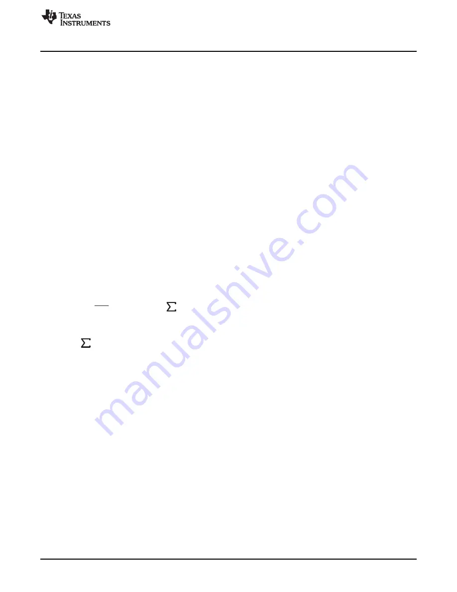
18.3.11.2 Oversampling Baud-Rate Mode Bit Timing
In oversampling baud-rate mode, calculation of the length of bit i T
bit,TX
[i] is based on the baud-rate
generator UCBRx, UCBRFx and UCBRSx settings:
Where:
≤
= Sum of ones from the corresponding row in
m
UCBRSx
[i] = Modulation of bit i of UCBRSx
This results in an end-of-bit time t
bit,TX
[i] equal to the sum of all previous and the current bit times:
To calculate bit error, this time is compared to the ideal bit time t
bit,ideal,TX
[i]:
t
bit,ideal,TX
[i] = (1/Baudrate)(i + 1)
This results in an error normalized to one ideal bit time (1/baudrate):
Error
TX
[i] = (t
bit,TX
[i] – t
bit,ideal,TX
[i]) × Baudrate × 100%
18.3.12 Receive Bit Timing – Error Calculation
Receive timing error consists of two error sources. The first is the bit-to-bit timing error similar to the
transmit bit timing error. The second is the error between a start edge occurring and the start edge being
accepted by the eUSCI_A module.
shows the asynchronous timing errors between data on
the UCAxRXD pin and the internal baud-rate clock. This results in an additional synchronization error. The
synchronization error t
SYNC
is between –0.5 BRCLKs and +0.5 RCLKs, independent of the selected baud-
rate generation mode.
489
SLAU272C – May 2011 – Revised November 2013
Enhanced Universal Serial Communication Interface (eUSCI) – UART Mode
Copyright © 2011–2013, Texas Instruments Incorporated