


Principle of Operation
15.2 Principle of Operation
The REF module provides all of the necessary voltage references that are used by various peripheral
modules throughout the system.
The high-performance bandgap has very good accuracy (factory trimmed), low temperature coefficient,
and high PSRR while operating at low power. The bandgap voltage is used to generate three voltages via
a noninverting amplifier stage, namely 1.5 V, 2.0 V, and 2.5 V. One voltage can be selected at a time.
One output is the variable reference line that can be used throughout the system. The variable reference
line provides either 1.5 V, 2.0 V, or 2.5 V to the rest of the system. A second output of the REF module
provides a buffered bandgap reference line that can be used by any module throughout the system. The
REF module includes the temperature sensor circuitry. The temperature sensor is used by an ADC to
measure a voltage proportional to temperature.
15.2.1 Low-Power Operation
The REF module is capable of supporting low-power applications such as LCD generation. Many of these
applications do not require a very accurate reference, compared to data conversion, yet power is of prime
concern. To support these kinds of applications, the bandgap is capable of being used in a sampled
mode. This reduces the average power of the bandgap circuitry significantly, at the cost of accuracy.
When not in sampled mode, the bandgap is in static mode. Its power is at its highest but so is its
accuracy.
Modules automatically can request static mode or sampled mode via their own individual request lines. In
this way, the particular module determines what mode is appropriate for its proper operation and
performance. Any one active module that requests static mode causes all other modules to use static
mode, even if another module is requesting sampled mode. In other words, static mode always has higher
priority over sampled mode.
15.2.2 REFCTL
The REFCTL registers provide a way to control the reference system from one centralized set of registers.
REFCTL is used to control the reference system.
summarizes the REFCTL bits and their effect on the REF module.
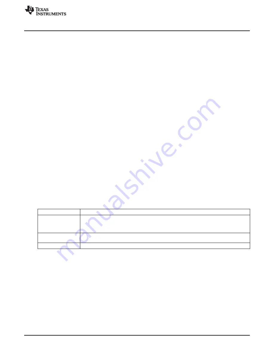
Table 15-1. REF Control of Reference System (REFMSTR = 1) (Default)
REF Register Setting
Function
Setting this bit enables the REF module, which includes the bandgap, the bandgap bias circuitry, and
the 1.5-V, 2.0-V, or 2.5-V buffer. Setting this bit causes the REF module to remain enabled even if no
REFON
module has requested it. Clearing this bits disables the REF module only if there are no pending
requests for any reference voltage.
Selects 1.5 V, 2.0 V, or 2.5 V to be present on the variable reference line when REFON = 1 or it is
REFVSEL
requested by any module.
REFTCOFF
Setting this bit disables the temperature sensor (when available) to conserve power.
15.2.3 Reference System Requests
There are three basic reference system requests that are used by the reference system. Each module can
use these requests to obtain the proper response from the reference system. The three basic requests are
REFGENREQ, REFBGREQ, and REFMODEREQ.
A reference request signal, REFGENREQ, is available as an input into the REFGEN subsystem. This
signal represents a logical OR of individual requests coming from the various modules in the system that
require a voltage reference to be available on the variable reference line. When a module requires a
voltage reference, it asserts its corresponding REGFENREQ signal. Once the REFGENREQ is asserted,
the REFGEN subsystem is enabled. After the specified settling time, the variable reference line voltage is
stable and ready for use. The REFVSEL settings determine which voltage is generated on the variable
reference line.
429
SLAU272C – May 2011 – Revised November 2013
REF Module
Copyright © 2011–2013, Texas Instruments Incorporated